Download
1 / 15
150 likes | 253 Views
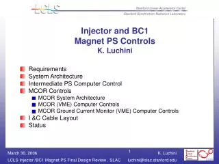
Detailed requirements and system architecture for injector and BC1 magnet power supply controls, including stability, temperature, I&C cable layout, and control systems integration.

E N D
Injector and BC1Magnet PS ControlsK. Luchini • Requirements • System Architecture • Intermediate PS Computer Control • MCOR Controls • MCOR System Architecture • MCOR (VME) Computer Controls • MCOR Ground Current Monitor (VME) Computer Controls • I &C Cable Layout • Status
Requirements • Magnet Power Supplies Stability • Bends and solenoids • Short term : 100 ppm RMS, over 1 second • Long term: 100 ppm RMS, over 10 seconds • Correctors, quads and trim coils • Short term: 30 ppm RMS, over 1 second • Long term: 400 ppm RMS, over 10 seconds • Temperature • System must operate in diurnal temp drifts of +/- 15 deg C (Linac gallery ) • Injector and BC1 for magnet systems will have separate controls and power • Fast feedback • Rate of 10Hz - for 4 of the Injector correctors • Sync timestamp w/beam pulse • Bipolar and Unipolar PS • Existing Magnets • Must be able to control from SLC and new EPICS control system • LI21 Quad String • Q21201 must run in opposite polarity in LCLS mode from SLC mode. • Q21301 will be set to zero in LCLS mode (hw installed).
EPICS IOC VME Crate Magnet Magnet Magnet Magnet System Architecture Linux VMS Alpha CA Server OPI SCP Standalones Ethernet (LCLSnet) (LEBnet) SLC net SLAC Ethernet PS Controller SLC Micro CAMAC MCOR Large PS Controller SCOR PS Bulk PS PS Bulk PS
Intermediate PS Controller System Architecture OPI Ethernet EPICS IOC Network Switch SLAC Ethernet PS Controller Terminal Server Interlocks Transductors Intermediate PS Magnet
MCOR Bulk PS System Architecturefor Magnets 30A and under Magnet Magnet EPICS IOC MCOR 12 VME Crate OPI OPI 16 Magnets@ 12Amps max MCOR Gnd Current Monitor MCOR Soft-Start Bulk PS
I/O Requirements • Analog Input: • Differential signal measurement • 16-bit resolution (15ppm), 16-channels per module • Bipolar +/- 10V • Conversion rate less than 1 millisecond for all channels • Extended temperature 4ºC (40ºF) to 45ºC (113ºF) • Analog Output • Updated channels simultaneously or individually • 16-bits resolution (15ppm), 16-channels per module • Bipolar +/- 10V • Extended temperature 4ºC (40ºF) to 45ºC (113ºF) • Digital Output • Optically Isolated • Largest expected voltage +24V • Extended temperature 4ºC (40ºF) to 45ºC (113ºF) • Digital Input • Optically Isolated • Largest expected voltage +24V • Extended temperature 4ºC (40ºF) to 45ºC (113ºF)
MCOR VME Controls • Acromag IP231-16E: MCOR (control) • Bipolar voltage +/- 10V • Independent D/A converter per channel with a 13 microsecond settle time • 16-bit resolution, 16-channels, single-ended • Temperature extended -40ºC (-40ºF) to 85ºC (185ºF) • Hytec IP-ADC-8413: MCOR (monitor) • Bipolar voltage +/- 10V • 16-bit resolution, 16-channel, differential • Temperature extended • Acromag IP-440-2E Digital Input: MCOR Ground Current Monitor (monitor) • 32-Channel • Input voltage range +/- 16V to +/- 40V • Optically Isolated • Temperature extended -40ºC (-40ºF) to 85ºC (185ºF) • Acromag IP-445-E Digital Output: MCOR Ground Current Monitor (control) • 32-Channel • Voltage range +/-60V • Optically Isolated • Temperature extended -40ºC (-40ºF) to 85ºC (185ºF)
MCOR VME Controls Continued • MVME6100 CPU – Power PC • Two Ethernet ports • Port 1: Channel Access - VLAN magnet • Port 2: Fast feedback - VLAN fast feedback • Two PMC slots • Slot 1: Event Receiver – Timing • Wiener VME-64X Crate with P0, Fan and Ethernet Control • Acromag AVME9670 - 64X IP Carrier (1 per MCOR crate) • 4 Ports • Acromag Tran-200: Transition Module • Install in rear of VME crate • 4 SCSI-2 Connectors (50-pin)
Trans-200 P1 Port D D Port C C P0 Port B B P2 Port A A MCOR Cable Layout Front View Rear View AVME9670 MCOR Crate P1 J4 J3 VME Backplane IP-ADC-8413 P0 DAC IP-231-16E P2
Trans-200 P1 Port D D Port C C P0 Port B B P2 Port A A MCOR Current MonitorCable Layout Front View Rear View AVME9670 MCOR Ground Current Monitor P1 VME Backplane P0 DO IP-445-E P2 DI IP-440-2E
List of VME Needed Note: **Contingency Included
Status • VME 64X Crates: ordered • VME Modules: ordered except for analog modules • PMC Modules • Evr: order pending • Network Switches: ordered • Terminal Servers: ordered • Inter-rack Cable Fabrication: not yet started • Drawings • EI drawings - TBD • VSIO drawing prototypes done • WI drawings -TBD • VISIO drawing prototypes done • CAPTAR coding for cable plant in