Magnet Controls K. Luchini
180 likes | 324 Views
Magnet Controls K. Luchini. Physics Requirements Engineering Requirements Technical Interfaces Hardware Hardware Alternatives Interface Control Requirements Software Block Diagram Schedule Test Plan Safety Hazards. Physics Requirements. Magnet Power Supplies

Magnet Controls K. Luchini
E N D
Presentation Transcript
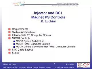
Magnet Controls K. Luchini • Physics Requirements • Engineering Requirements • Technical Interfaces • Hardware • Hardware Alternatives • Interface Control Requirements • Software Block Diagram • Schedule • Test Plan • Safety Hazards
Physics Requirements • Magnet Power Supplies • Stability/regulation: PS long term average signal • Correctors: 0.1% of maximum current( e.g.10 e-3, 1000ppm) • Bends: 0.05-0.1% of maximum current • Temperature • Diurnal temperature drifts must not exceed +/- 15 degC (Linac gallary is of concern) • Injector hut - temperature controlled racks will maintain a temperature of 72degC +/-1degC • Polarity • Bipolar and Unipolar PS • Pulsed Supplies are all unipolar (BXKIK, BYKIK) • PRD for Polarity Conventions by Paul Emma • Defines positive and negative polarity • Describes how to connect up polarity to terminals on magnet • Permanent stickers to designate the positive and negative terminals on magnets • Existing Magnets • Many SLC magnets will be turned off during LCLS operation • LI21 Quad String • Q21201 must run in opposite polarity in LCLS mode from SLC mode. • Q21301 will be set to zero in LCLS mode (hw installed).
Physics Requirements Cont. • LI24 Quad String • Q24201 – Remove Q24601,Q24701,Q24801 & Q24901 from string • Q24601 needs independent PS • Add two new strings (Doubled up QE magnets) • Q24701A,Q24701B, where Q24701 becomes Q24701A & Q24801 becomes Q24701B • Q24901A,Q24901B, where Q24901 becomes Q24901A & Q24901B is a new magnet • Magnet Correctors with Feedback – total of 20 w/4@ 120Hzl • Maximum rate of 120Hz • Achieve 80-90% of desired B-field with a net change of • Injector, Linac and Undulator: 260mA • LTU: 100mA • Injector YC04,XC04,YC07,XC07 10Hz w/precision of 10% of rms beam size • Linac LI21 XC2402,YC21503,XC21802,YC21900 10Hz w/precision of 10% of rms beam size • Linac LI24 YC2400 10Hz w/precision of 10% of rms beam size • Linac LI25 XC25202,XC25602,YC25503 10Hz w/precision of 10% of rms beam size • LTU XCQT32,YCQT32,SCDL4,YCQT42 120Hz w/precision of 5% of rms beam size • Undulator XCUM1,YCUM2,XCUM4,YCUM3 0.1-0.01Hz w/precision of 10% of rms beam size
Engineering Requirements • Magnet Power Supply Families • Reduce Family of PS for ease of maintenance and cost • 60V, 165A, 10kW • 25V,375A,10kW • 33V,300A,10kW • Magnet Interlocks including Ground fault protection will be provided • Control Interface hardware VME or embedded processors w/PMC or PCI • Standard VME w/o P0 • CPU w/ two Ethernet ports • I/O • Option to obtain signals from P2 • Analog Input: • Differential signal measurement (requires 2-pins on P2) • Minimum true 16-bit resolution (15ppm) • Minimum 16-channels per module • Configurable or auto scanning as bipolar, unipolar 0-5V,0-10V,+-5V,+/- 10V
Engineering Requirements Cont. • Individual channel gain programmable • 100KHz throughput in single channel mode • Scan rate 1MHz update rate • Auto scanning for multiple channels • Latency 1ms • Analog Output • Updated simultaneously or individually • Minimum 16-bits (15ppm) • Minimum 16-channels per module • Conversion or auto scanning as bipolar, unipolar 0-5V,0-10V,+-5V,+/- 10V • Digital Input • Optically Isolated • Largest expected voltage +24V (5,10,24V) • Interruptible inputs • Digital Output – Acromag IP445 (32 channel) • Optically Isolated • Largest expected voltage +24V (5,10,24V)
Engineering Requirements • Second Transductor • Supplied for large and intermediate PS - Quads, Bends • Not supplied for correctors or trim coils • Bulk Supplies • Used for correctors and bend/quad trims • Reduced price • Redundancy • PCD currently developing and desiging for MCOR system • No redundancy provided for large or intermediate PS • Stability of controller 15ppm/degC • Ground Fault • Switching between LCLS mode and SLC mode must not exceed 15 minutes • All magnets terminals will be covered (see Wayne’s Basis of Estimate Reports) • Ripple provided every 10 seconds • Fast feedback @120Hz • 8us total time • 5us to set desired current, including settle time – 80-90% of desired current
Technical Interface • Physicist • Paul Emma • Patrick Krejcik • Roger Carr • Mark Woodley – Modeling ( SLC db needed Jan 2006 for Injector/BC1) • Geoff Pile (APS) • Operations – Date Controls Needed is Aug 2006 • Mike Stanek – SLC Interface • Arturo Alarcon • Stephen Schuh • Power Conversion Department – Date Controls needed is Feb 2006 • Paul Bellomo • Antonio de Lira • Dave MacNair • Engineering • Bob Fuller - one man does all • Carl Rago – Mechanical • John Dusatko - Electrical • Mike Cecere – Electrical • Mario Ortega – Racks & Cabling • Patrick Bong - PPS
Technical Interface Cont. • Magnet Measurements • Zack Wolf • Scott Anderson • Conventional Facilities • Javier Sevilla – Linac • Bob Law – Injector • Lori Shewchuk – Master Motor Controller for Injector/BC1 • Software • Shen Peng • Stephanie Allison – SLC Aware IOC & Fast Feedback • Debbie Rodgin – SLC Aware IOC • Diane Fairley – High Level Applications • Stephen Norum - MPS • Argonne Inteface • Josh Stein - Undulator • SLC Interface • Ken Underwood • Nancy Spencer (SLC db needed Dec 2005 for Injector/LI21) • Ron Chestnut
Hardware • VME • Crate • Wiener - 24 Slot • Dawn 6100 - 2 Slot (This is VME 64X) • Motorola Mvme6100 • Embedded CPU - under investigation PC104 Plus, ColdFire • SBS VIPC627 IP Carrier (4-ports) • Acromag IP330 ADC 16-channel, BiRa VSAM 16-bit • Acromag IP231 DAC 16-Channel • Acromag IP440 Digital Input 32-channnel • Acromag IP445 Digital Output 32-channel • Intermediate PS Controller • SLAC Ethernet Controller – Dave MacNair • Provides ps regulation, ramp rate, health of ps • Temperature stability 2ppm/degC • MCOR System • 15ppm/degC • MCOR 12/30A • No ground fault (circuitry to be added by PCD) • No redundancy provided for large or intermediate PS
Hardware Alternative • SNS PS Controllers • Price good • Not able to use in Linac due to diurnal temperature drifts in summer • PS expected to do regulation • PSI Controllers • Too expensive • PS expected to do regulation • APS PS Controller • Still under development • PS expected to do regulation • Upgrade SLAC Ethernet Controller • Embedded IOC – pc104 plus, coldFire processors • FPGA for regulation code,etc • Hardware Knob Boxes – ESD group Ron Chestnut
Interface Control • Fast feedback • 20 Correctors at a maximum rate of 120Hz • 8ms between pulses total • 5ms to set magnet B-field within 80-90% of desired • No EVR modules required in magnet IODC • Status read back of DAC setting provide to fast feedback within 1 millisecond (ms) • Use second Ethernet port on switch VLAN for communication between BPM and Magnet IOC’s • MPS • Design underway by Stephen Norum • Bends strings only – bulks • Injector: BXH1,BXH2,BXH3,BXH4 • Linac LI21: BX11,BX12,BX14,BX14 • I/O Signals required • Digital on/off status of PS • Analog Input (including transductor) • TBD if data is retrieved from the EPICS db or directly from hw • PPS • All magnets will have their magnet electrical connections covered such that power systems comply with SLAC, National Electric Code and OSHA regulations. • No provisions for interlocking magnet power supplies for magnet safety.
Schedule • Software – Phase I • Magnet Functions: • Trim, Calibrate, Standardize, Degauss, Ptrb – Feb 2006 • Knobs - from scp and sliders from EPICS • Diagnostic Calibrate • PS On/Off • Interlock Reset • SLC Aware IOC Magnet Control and Monitor (Debbie Rogind) - Done • SLC db • Only for Injector, Linac and BSY magnets • Injector and BC1 needed Dec 2005 for Modeling • SLC Micro • Small changes – K. Underwood Feb 2006 • EPICS drv. & dev. Support - End of Dec 2005 • EPICS db and Sequences Jan 2006 • Fast Feedback – Oct 2006 • New High Level Applications – Oct 2006
Schedule Cont. • PS and controllers • Specification: July 2005 • Purchasing: Injector/LI21 Aug-Oct 2005 • Delivery: Jan-Feb 2006 • PS Testing • Bench testing in building – no software needed • Assemble racks in building 24 – software controls required (trim, calib, stdz, ptrb) • Install racks and magnets for Injector – Jan-Feb 2006 • Install magnets for LI21 – Aug 2006 • Integration: Mar-Apr 2006 • Cables connected – Hookup magnet and PS • Turn on and check out magnets • Phase I: Aug-Nov 2006 (4 month down period) • Integration of Linac • Installation of magnets and ps in BC1 • Cables connected in BC1 – hookup magnets • Turn-on and checkout magnets in BC1 • Commissioning: Dec 2006-Aug 2007
Test Plan • Modeling - Mark Woodley • Bench testing of PS systems • Will not require controls software • Magnet PS Assembled in Racks before installation • PS connected to a dummy load • Functions to check out supply • Turn On • Turn Off • Reset Interlocks • Perturb • Trim • Calibrate • Standardize • Magnet PS Installation • PS connected to a real load • Functions to check out supply • Turn On • Turn Off • Reset Interlocks • Perturb • Trim • Calibrate • Standardize
Safety Hazards • Electrical Hazards