The Medium Access Control Sublayer
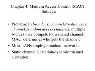
The Medium Access Control Sublayer. Chapter 4. The Channel Allocation Problem. Static Channel Allocation in LANs and MANs Dynamic Channel Allocation in LANs and MANs. Dynamic Channel Allocation in LANs and MANs. Station Model. Single Channel Assumption. Collision Assumption.

The Medium Access Control Sublayer
E N D
Presentation Transcript
The Medium Access ControlSublayer Chapter 4
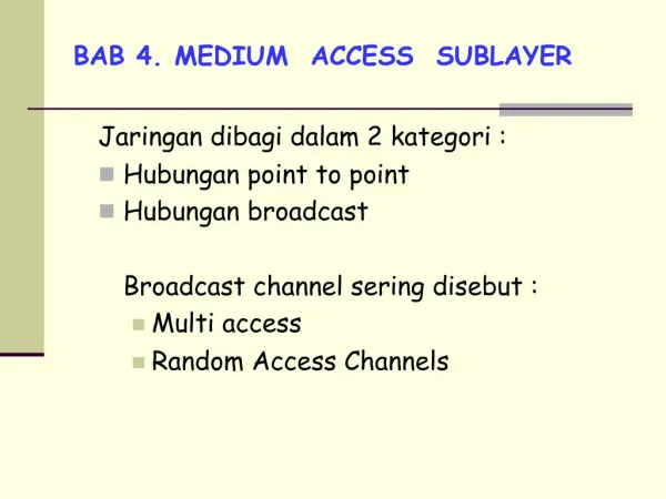
The Channel Allocation Problem • Static Channel Allocation in LANs and MANs • Dynamic Channel Allocation in LANs and MANs
Dynamic Channel Allocation in LANs and MANs • Station Model. • Single Channel Assumption. • Collision Assumption. • (a) Continuous Time.(b) Slotted Time. • (a) Carrier Sense.(b) No Carrier Sense.
Multiple Access Protocols • ALOHA • Carrier Sense Multiple Access Protocols • Collision-Free Protocols • Limited-Contention Protocols • Wireless LAN Protocols • Wavelength Division Multiple Access Protocols • Broadband Wireless • VLANS/Bridge Spanning Tree
Wavelength Division Multiple Access Protocols Wavelength division multiple access.
Wireless LAN Protocols A wireless LAN. (a) A transmitting. (b) B transmitting.
Wireless LAN Protocols (2) The MACA protocol. (a) A sending an RTS to B. (b) B responding with a CTS to A.
Gigabit Ethernet (a) A two-station Ethernet. (b) A multistation Ethernet.
Gigabit Ethernet (2) Gigabit Ethernet cabling.
IEEE 802.2: Logical Link Control (a) Position of LLC. (b) Protocol formats.
Wireless LANs • The 802.11 Protocol Stack • The 802.11 Physical Layer • The 802.11 MAC Sublayer Protocol • The 802.11 Frame Structure • Services
The 802.11 Protocol Stack Part of the 802.11 protocol stack.
The 802.11 MAC Sublayer Protocol (a) The hidden station problem. (b) The exposed station problem.
The 802.11 MAC Sublayer Protocol (2) The use of virtual channel sensing using CSMA/CA.
The 802.11 MAC Sublayer Protocol (3) A fragment burst.
Broadband Wireless • Comparison of 802.11 and 802.16 (and radio telephony • Design goals are very different! • Fixed vs mobile, antenna, radio cost, distance, sectoring, traffic/QoS • The 802.16 Protocol Stack • The 802.16 Physical Layer • The 802.16 MAC Sublayer Protocol • The 802.16 Frame Structure
The 802.16 Protocol Stack The 802.16 Protocol Stack. OFDM in 2GHz and 5 GHz
The 802.16 Physical Layer The 802.16 transmission environment.
The 802.16 Physical Layer (2) Frames and time slots for time division duplexing.
The 802.16 MAC Sublayer Protocol Service Classes • Constant bit rate service • Real-time variable bit rate service • Non-real-time variable bit rate service • Best efforts service
The 802.16 Frame Structure (a) A generic frame. (b) A bandwidth request frame.
Bluetooth • Bluetooth Architecture • Bluetooth Applications • The Bluetooth Protocol Stack • The Bluetooth Radio Layer • The Bluetooth Baseband Layer • The Bluetooth L2CAP Layer • The Bluetooth Frame Structure
Bluetooth Architecture Two piconets can be connected to form a scatternet.
Bluetooth Applications The Bluetooth profiles.
The Bluetooth Protocol Stack The 802.15 version of the Bluetooth protocol architecture.
The Bluetooth Frame Structure A typical Bluetooth data frame.
Data Link Layer Switching • Bridges from 802.x to 802.y • Local Internetworking • Spanning Tree Bridges • Remote Bridges • Repeaters, Hubs, Bridges, Switches, Routers, Gateways • Virtual LANs
Data Link Layer Switching Multiple LANs connected by a backbone to handle a total load higher than the capacity of a single LAN.
Bridges from 802.x to 802.y Operation of a LAN bridge from 802.11 to 802.3.
Bridges from 802.x to 802.y (2) The IEEE 802 frame formats. The drawing is not to scale.
Local Internetworking A configuration with four LANs and two bridges.
Spanning Tree Bridges Problem of Packet forwarding loops with multiple bridges Two parallel transparent bridges.
Spanning Tree Bridges (2) (a) Interconnected LANs. (b) A spanning tree covering the LANs. The dotted lines are not part of the spanning tree.
IEEE 802.1D • Algorithm due to Pearlman et al to construct spanning tree in a distributed manner.
IEEE 802.1D • Basic ideas • Node with least id becomes root • For a given lan, bridge/port with least cost on path to root becomes the designated active bridge, all others are passive • Bridges broadcast configuration BPDUs with id of self, id of presumed root, cost to root. Each bridges starts by believing it is root. • If you get superior information on your presumed root path, forward downstream • If you get inferior information, reply with yours
Remote Bridges Remote bridges can be used to interconnect distant LANs.
Repeaters, Hubs, Bridges, Switches, Routers and Gateways (a) Which device is in which layer. (b) Frames, packets, and headers.
Repeaters, Hubs, Bridges, Switches, Routers and Gateways (2) (a) A hub. (b) A bridge. (c) a switch.
Virtual LANs A building with centralized wiring using hubs and a switch.
Why VLANs if everything interconnects? • LAN represents organizational hierarchy rather than geography • Security • Traffic Load/separation (research vs production) • Limiting Broadcasts • Legitimate (i.e ARP) • Storms • Do “rewiring” in software
Virtual LANs (2) (a) Four physical LANs organized into two VLANs, gray and white, by two bridges. (b) The same 15 machines organized into two VLANs by switches.
Grouping into VLANs • Port level mapping • All machines on a port must be on the same VLAN – OK with completely switched networks. • MAC level mapping • What if “docks” are used with notebooks • IP level mapping • Violates layering
802.1q issues • Can we identify the VLAN in the frame header • Easy to do for new protocols, define a new header field • What to do with (Old/Fast/Giga) Ethernet, which has no “free” header fields and max size frames ? • Who generates this field • What to do with legacy NICs • Key point – this field is only used by switches, not end machines
802.1Q • Adds a new field to Ethernet header circa 98, raised frame size to 1522 from 1518 • 1st 2 bytes are protocol ID, fixed as 0x8100 (>1500 so type) • 2nd byte has VLAN id (lower order 12 bits), 3 bit priority (used by 802.1P), 1 bit CFI to indicate 802.5 traffic • Required Bridges and switches to be VLAN aware, “future” NICs should be aware too (with Giga deployment?) • Bridges/switches could add this field till then)
The IEEE 802.1Q Standard Transition from legacy Ethernet to VLAN-aware Ethernet. The shaded symbols are VLAN aware. The empty ones are not.
The IEEE 802.1Q Standard (2) The 802.3 (legacy) and 802.1Q Ethernet frame formats.
UWB • FCC definition – bandwidth > 25% of center frequency. • 2(Fh-Fl)/(Fh+Fl) • 802.11b has 80MHz of usable spectrum in 2.4GHz band • Uses Pulse position Modulation • Low power on any particular frequency, fitting in under FCC Part 15 rules • MAC issues – QoS, TDMA and CDMA don’t work well. P802.15.3, HiperLAN DM
Summary Channel allocation methods and systems for a common channel.