Chapter 4: The Medium Access Sublayer
This chapter covers the basics of the Medium Access Control (MAC) sublayer, including channel allocation issues, multiple access protocols like ALOHA and CSMA, collision detection, and collision-free protocols. It examines the trade-offs between throughput, delay, and channel efficiency in LANs, MANs, and high-speed networks. Different scenarios, such as static vs. dynamic channel allocation, persistence in CSMA, and collision-free strategies, are discussed, along with their impact on network performance.

Chapter 4: The Medium Access Sublayer
E N D
Presentation Transcript
Chapter 4: The Medium Access Sublayer CS 455/555: Spring 2007
Topics to be covered • Introduction • Channel Allocation problem • Multiple Access Protocols • IEEE Standard 802 for LANs • Bridges • High-speed LANs • Satellite Networks
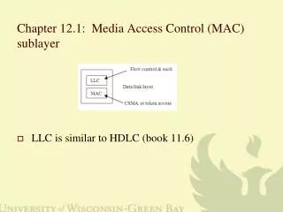
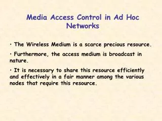
Introduction • Medium Access Control (MAC) sublayer is part of Data Link layer. • In fact, it is the bottom part of DLL (interfacing with the physical layer) • This chapter deals with broadcast networks
Channel Allocation problem • Static Channel Allocation in LANs and MANs Mean delay T = 1/(μC-λ) (Single channel) Mean delay T’ = N/(μC- λ) = NT (N channels) • Dynamic Channel Allocation in LANs and MANs * Station Model * Single Channel assumption * Collision assumption * Continuous Time vs. Slotted time * Carrier sense vs. No carrier sense
Multiple Access Protocols • ALOHA: Shared satellite channel • Pure ALOHA: Let users transmit whenever they have data to be sent • Issues: Contention, collision detection, retransmission • Vulnerable period for a frame • If G is the mean number of transmission attempts (old and new) per frame time (offered load), S is the throughput per frame time, then S = Ge-2G for pure ALOHA. • Maximum throughput occurs at G = 0.5 with S=1/(2e)=0.1839. I.e., maximum channel utilization is 18 percent.
Multiple Access Protocols (Cont.) • Slotted ALOHA: Divide the time into discrete intervals, each interval corresponding to one frame. • Obviously, there may be a special signal needed to synchronize the clocks at all stations. • S=Ge-G • Maximum throughput occurs at G=1, S=1/e or 0.368. This is twice that of pure ALOHA protocol. • The expected number of transmissions per user frame is eG. So when G=1, each user frame needs e or 2.72 attempts.
Multiple Access Protocols (Cont.) • Carrier Sense Multiple Access protocols (CSMA): Station listens for a carrier and acts accordingly • Persistent and Non-persistent CSMA: 1-persistent CSMA, p-persistent CSMA, non-persistent CSMA • 1-persistent: Keep sensing carrier until it is found idle; transmit immediately; if collision, wait a random amount of time and try again. The non-zero propagation and multiple stations sensing idle carrier are the main reasons for collisions. • Non-persistent: If a station senses carrier busy, it will wait for a random amount of time and senses again. This step is repeated until it finds it free when it transmits its frame. • P-persistent: Applies to slotted channels: Whenever a station finds a slot free, it only transmits with probability p. This step is repeated for every empty slot.
Collision-Free Protocols • Bit-map protocol • Binary countdown • Limited Contention Protocols • Adaptive Tree walk protocol
Multiple Access Protocols (Cont.) • CSMA with Collision Detection (CSMA/CD) • Here, stations stop their transmissions as soon as they detect a collision. • How long will it take for a station to detect a collision after it starts transmitting? This depends on the maximum propagation delay between itself and any other station. • If τ is the maximum distance (in time) between stations, then if one station started just before the other one (at τ distance) ended. While the 2nd station may detect a collision very soon, the 1st station would only detect it when the 2nd stations attempt reaches it. Thus the 1st one can’t detect a collision until after (2 τ -ε) of its starting of transmission. • No MAC layer protocol guarantees reliable delivery.
Multiple Access Protocols (Cont.) • Collision-free protocols: Assumes a fixed number of stations (N) each with a unique address 0..N-1 wired into hardware. Uses contention slots where stations can broadcast their intent to transmit. • A Bit-map protocol: Contention (or reservations) slots (bits 0..N-1) followed by actual transmission of data frames (d bits each). • At low load, channel efficiency = d/(d+N), since d data bits are transmitted for every N bits of contention slots. • At high load, channel efficiency = N.d/(Nd+N)=d/(d+1)
Multiple Access Protocols (Cont.) • Binary countdown: This scheme attempts to eliminate the contention slot overhead • Each station has a unique binary address. Stations who wish to contend for a slot transmit their address bit by bit prior to actual data frame transmission. If a station with a 0-bit contends with a 1-bit, then the station that sent “0” stops contention. This continues until the last address bit is transmitted. The station that successfully stayed until the end, uses the next data frame to send its data frame. • In this case, if there are n-bits in the address, then it would take n-bit slots prior to each data frame.
Multiple Access Protocols (Cont.) • Evaluation metrics for MAC protocols: • Delay and (ii) Channel efficiency CSMA vs. Collision protocols: CSMA offers low-delay at low-loads and low channel efficiency at high-loads. Contention-free protocols offer high-delay at low-load and high efficiency at high-loads. • Is there a way to benefit at both low and high loads?
Multiple Access Protocols (Cont.) • Limited contention protocols: Limit the number of stations contending for a slot---thus we will have groups of stations eligible to contend for each slot (e.g., 1 in the case of binary countdown, and N in the case of ALOHA, or some 1≤x ≤ N in the case of limited contention) • Adaptive Tree Walk Protocol: Assume the stations to be organized in a tree (say using the bits in their addresses). During slot 0, all stations with root as an ancestor contend; if there is no collision; then the successful station will send the data frame. Otherwise, those under node 2 will only contend. If there is none, then the one under node 3 will contend; this will continue until a successful transmission. • Several variations of the basic protocol exist.
IEEE Standard 802 For LANs and MANs • IEEE 802.3 Standard: CSMA/CD LAN: Ethernet • IEEE 802.4 Standard: Token Bus • IEEE 802.5 Standard: Token Ring
IEEE Standard 802.3 • 1-persistent CSMA/CD: A station keep listening to the cable until it is idle; it then starts transmitting its data frame; the moment it detects a collision, it terminates its transmission; after a collision, a station waits for a random time and starts repeating the above steps. • Ethernet is only one product that follows the 802.3 standard. There could be several variations of this one.
IEEE Standard 802.3 (Cont.) • Notation for the cable: 10Base5 means 10Mbps bandwidth and a maximum length of 500 meters per segment. • Segments may be connected via repeaters. • Restriction: A system may contain multiple cable segments and multiple repeaters, but no two transceivers may be more than 2.5 km apart and no path between any two transceivers may traverse more than four repeaters.
IEEE Standard 802.3 • Encoding binary signals on the cable: Somehow each receiver should know what a bit period is and what its value is. • Manchester encoding: Each bit period is sent as two levels: high (1st half) and low (2nd half) for bit “1”; and reverse for bit “0”. So there is a transition for every bit received. Easy for receiver to synchronize with sender. • 001011: Will be sent as LHLHHLLHHLHL where H is high- and L is low-signal.
IEEE Standard 802.3 • Differential Manchester Encoding: Bit 1 has no transition at the beginning and bit 0 has a transition at the beginning. • 001011 will be sent as (assume that prior to sending the 1st 0 bit, the level was H): LHLHHLHLLHHL • Differential offers better noise immunity. • All 802.3 baseband systems use Manchester encoding
IEEE Standard 802.3 • 802.3 MAC Sublayer protocol: Format: source and destination addresses, length of data, data, checksum, and a 7-byte preamble. • 6-byte address: 48-bits: High-order bit (47th bit) of the destination address used for broadcast/multicast purposes; the 46th bit is used to distinguish local for global addresses. Thus 46-bits are used to uniquely identify a station in the entire world. • Valid frames must be at least 64 bytes long (excluding preamble and start of frame delimiter) • Why the minimum length limitation? Goes back to the 2τ argument we had with respect to CSMA/CD.
IEEE Standard 802.3 • Importance of minimum of 2 frame length: Suppose a station A at one end of the cable begins a transmission at time t=0; A station B at a distance of from A can listen to the 1st bit only at time t= . If it started transmitting at time t= -, just before sensing bit-1 of A, then this event would take another time to reach A. That is only at t=2 - A can sense that there was a collision. If we want A to detect a collision before it completes transmitting its frame, the transmission time should be at least 2 . Thus minimum frame length = 2*Maximum propagation time*speed of transmission.
IEEE Standard 802.3 (Cont.) • With a maximum length of 2.5 km, maximum of 4 repeaters and 10 Mbps speed, the minimum transmission time is 51.2sec. If a frame has fewer than 64 bytes, it is padded. • For a 2500-meter 1-Gbps LAN, minimum frame length will be 6400 bytes. • For a 250meter 1-Gbps LAN, minimum is 640 bytes. • Problem: Given the length of the cable, speed of propagation, and the speed of transmission, you should be able to determine the minimum length of a frame.
IEEE Standard 802.3 (Cont.) • Binary exponential back-off algorithm: Once a collision is detected what should a station do? • After the 1st collision, pick 0 or 1 randomly and wait for that many slots before attempting again. • After the 2nd collision, pick randomly from 0-3, and wait for that many slots before attempting again. • After I collisions, a random number between 0 and 2i-1 is chosen and that number of slots is skipped. • This freezes when maximum slots is 1023.
IEEE Standard 802.3 (Cont.) • Performance of 802.3 protocol • Channel efficiency = T/(T+2P/A) where T is the mean time to transmit a frame, P is the maximum propagation time, and A is the probability that some stations occupy the channel in a slot. When the number of stations is large, you can assume that A=1/e. • Also, channel efficiency=1/(1+2BLe/cF) • Where B is the bandwidth (bps), F is the frame length (in bits), c is the speed of propagation (in km/sec), L is the length of the cable (in km), and e=2.718.
Wireless LANs • IEEE 802.11 standard for wireless LANs • with base station/without base station or ad hoc networking (Fig. 1-35) • Difference between wired Ethernet and wireless LAN: radio range is limited (Fig. 1-36) • Protocol stack (Fig. 4-25)
802.11 MAC Sublayer Protoocl • Hidden station problem (Fig. 4-26a) • Exposed station problem (Fig. 4-26b) • DCF (Distributed coordination function) • PCF (Point coordination function)---use base station
DCF • CSMA/CA---CSMA with collision avoidance • Physical channel sensing---Listen before transmitting; if collision, wait a random time and sense again • Virtual channel sensing---MACAW (Fig. 4-27) • In Fig. 4-27, A,B are in range; A,C are in range; and C and D are in range • Frames are fragmented to minimize errors; fragments are individually ACKed (Fig. 4-28)
PCF • Base station polls other stations • No collisions occur due to centralized control
802.11 Data Frame Format • Fig. 4-30 • Frame control • Duration: How long the channel will be busy (NAV) • Address1, 2—SRC and DST • Address 3,4---Base stations of SRC and DST
BLUETOOTH • Short-range, low-power, inexpensive radios • Piconet—basic unit—Master node and up to 7 slave nodes within a distance of 10 meters; all communication is master-slave; not slave-slave • Multiple piconets can coexist in the same room; they may be connected via bridge nodes forming a scatternet • Up to 255 parked nodes in the net
Bridges • Means to interconnect individual LANs • Operate at the data link layer • Reasons for bridges: pages 318-319specify six reasons: (1) autonomous divisions (2) different buildings (3) logical grouping (4) physical distance (5) Reliability (6) Security • Issues in bridging different LANs: (i) Different frame format (ii) different data rates (iii) Timers at higher layers (iv) different maximum frame lengths
Bridges • Example: Fig. 4-40: 802.11 to 802.3 • Problems: See pages 320-321
Transparent Bridges • A bridge must decide whether to discard a frame or forward it to another LAN • Maintains a hash table to know where different sources are located • Initially, hash table is empty---it has to flood everything to everyone else • It then learns as to which side the sources are---backward learning • Outdates hash tables may be purged periodically • Two or more bridges connecting two LANS: Possible loops; avoided by using a spanning tree of bridges; the spanning tree is built with bridges and LANs; some bridges may be left out in this process
Source Routing Bridges • CSMA/CD and token bus accepted transparent bridges • The token ring community went for source routing bridges • Here, the source determines the path that a message should take • When a destination is unknown, the source issues a discovery frame which is forwarded to every LAN on the internetwork. When the reply comes back, the bridges record their identity in it, so the original sender can know the path. • Comparison bridges: See pages 316-317
Remote Bridges • Used when individual LANs are far apart • In this case bridges on each Lan are connected via point-to-point links
High-speed LANs • FDDI—Fiber distributed data interface---100 Mbps; up to 200 km; up to 1000 stations; can be used as a backbone to connect copper LANs • Fast Ethernet: 802.3u: reduce bit time from 100 nsec to 10 nsec (nsec --- nanoseconds)