Download
1 / 61
610 likes | 777 Views
The Medium Access Control Sublayer. Chapter 4. The Channel Allocation Problem. Static Channel Allocation in LANs and MANs Dynamic Channel Allocation in LANs and MANs. Dynamic Channel Allocation in LANs and MANs. Station Model.

E N D
The Medium Access ControlSublayer Chapter 4
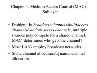
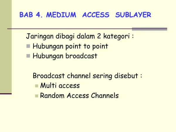
The Channel Allocation Problem • Static Channel Allocation in LANs and MANs • Dynamic Channel Allocation in LANs and MANs
Dynamic Channel Allocation in LANs and MANs • Station Model. N independent stations sending messages according Poisson distribution. • Single Channel Assumption. A single channel is available to all stations to transmit to and receive from. • Collision Assumption. If stations transmit at the same time frames will collide and garbled. All stations can detect collision and retransmit frame later. • (a) Continuous Time: Frame can start transmission at any time. (b) Slotted Time: Frame can start transmission at given time instance. • (a) Carrier Sense: Stations can sense if the channel is in use and wait.(b) No Carrier Sense: Stations cant tell if the channel is free.
Multiple Access Protocols • ALOHA • Carrier Sense Multiple Access Protocols • Collision-Free Protocols • Limited-Contention Protocols • Wavelength Division Multiple Access Protocols • Wireless LAN Protocols
Pure ALOHA In pure ALOHA, frames are transmitted at completely arbitrary times.
Collision conditions in pure Aloha If another frame starts here we will have collision period is 2t All frames are of the same size. Frame transmission can start at any time instant.
Throughput versus offered traffic for ALOHA systems. (throughput per packet time) Max throughputs: 18% at G = 0.5 for pure 37% at G = 1 for slotted.
Persistent and Non-persistent CSMA carr -> check next slot carr ->check next slot (1-p) carr ->random back off carr -> check after random time no carr -> transmit with prob p. no carr -> transmit p-persistent is slotted nonpersistent
CSMA with Collision Detection CSMA/CD can be in one of three states: contention, transmission, or idle. Minimum contention slot is 2t where t is the propagation delay between the two most remote stations.
The binary countdown protocol . A dash indicates silence.
Wireless LAN Protocols A wireless LAN. (a) A transmitting. (b) B transmitting.
Wireless MACA (Multiple Access with Collision Avoidance) • C hears RTS to B 30 bytes frame with the length of the frame to follow. • D hears B responding with a CTS to A (copying the length of the next frame). • A starts transmitting.
Ethernet • Ethernet Cabling • Manchester Encoding • The Ethernet MAC Sublayer Protocol • The Binary Exponential Backoff Algorithm • Ethernet Performance • Switched Ethernet • Fast Ethernet • Gigabit Ethernet • IEEE 802.2: Logical Link Control • Retrospective on Ethernet
Ethernet 802.3 Base band Segment length in hundredths meters 10 MHz Vampire taps T conn.
Ethernet Cabling Three kinds of Ethernet cabling. (a) 10Base5, (b) 10Base2, (c) 10Base-T.
Ethernet coding (a) Binary encoding, (b) Manchester encoding, (c) Differential Manchester encoding.
Ethernet MAC Sublayer Protocol • Address bit 46 determines local or global address. • Min frame is 64 bytes from dest. address to checksum. Frame formats. (a) DIX Ethernet, (b) IEEE 802.3.
Collision detection can take as long as 2t This is to sense a collision before end of the frame reach far end. In 10 Mbps LAN 1 bit is 100 nsec, and max segment 2500 m round trip delay is 2t = 50 mksec = 500 bits = 64 bytes.
Binary exponential backoff Contention period Contention period Idle period Frame Frame Frame Frame p = 1/2 p = 1/4 p = 1/8 If k stations contend for a channel probability that any of k gets a channel is: A = kp(1 – p)k-1 p = 1/kgives Amax Average number of contention slots = S000 jA(1 – A)j-1 = 1/A. Therefore, channel efficiency = P/(P + 2t/A)
Ethernet Performance Efficiency of Ethernet at 10 Mbps with 512-bit slot times.
Switched Ethernet A simple example of switched Ethernet.
Fast Ethernet The original fast Ethernet cabling.
Gigabit Ethernet (a) A two-station Ethernet. (b) A multistation Ethernet.
Gigabit Ethernet (2) Gigabit Ethernet cabling.
IEEE 802.2: Logical Link Control (a) Position of LLC. (b) Protocol formats.
Wireless LANs • The 802.11 Protocol Stack • The 802.11 Physical Layer • The 802.11 MAC Sublayer Protocol • The 802.11 Frame Structure • Services
The 802.11 Protocol Stack Part of the 802.11 protocol stack.
The 802.11 MAC Sublayer Protocol (a) The hidden station problem. (b) The exposed station problem.
The 802.11 MAC Sublayer Protocol (2) The use of virtual channel sensing using CSMA/CA.
The 802.11 MAC Sublayer Protocol (3) A fragment burst.
The 802.11 MAC Sublayer Protocol (4) Interframe spacing in 802.11.
The 802.11 Frame Structure The 802.11 data frame.
802.11 Services Distribution Services • Association • Disassociation • Reassociation • Distribution • Integration
802.11 Services Intracell Services • Authentication • Deauthentication • Privacy • Data Delivery
Broadband Wireless • Comparison of 802.11 and 802.16 • The 802.16 Protocol Stack • The 802.16 Physical Layer • The 802.16 MAC Sublayer Protocol • The 802.16 Frame Structure
The 802.16 Protocol Stack The 802.16 Protocol Stack.
The 802.16 Physical Layer The 802.16 transmission environment.
The 802.16 Physical Layer (2) Frames and time slots for time division duplexing.
The 802.16 MAC Sublayer Protocol Service Classes • Constant bit rate service • Real-time variable bit rate service • Non-real-time variable bit rate service • Best efforts service
The 802.16 Frame Structure (a) A generic frame. (b) A bandwidth request frame.
Bluetooth • Bluetooth Architecture • Bluetooth Applications • The Bluetooth Protocol Stack • The Bluetooth Radio Layer • The Bluetooth Baseband Layer • The Bluetooth L2CAP Layer • The Bluetooth Frame Structure
Bluetooth Architecture Two piconets can be connected to form a scatternet.
Bluetooth Applications The Bluetooth profiles.
The Bluetooth Protocol Stack The 802.15 version of the Bluetooth protocol architecture.
The Bluetooth Frame Structure A typical Bluetooth data frame.
Data Link Layer Switching • Bridges from 802.x to 802.y • Local Internetworking • Spanning Tree Bridges • Remote Bridges • Repeaters, Hubs, Bridges, Switches, Routers, Gateways • Virtual LANs
Data Link Layer Switching Multiple LANs connected by a backbone to handle a total load higher than the capacity of a single LAN.
Bridges from 802.x to 802.y Operation of a LAN bridge from 802.11 to 802.3.
Bridges from 802.x to 802.y (2) The IEEE 802 frame formats. The drawing is not to scale.