Download
1 / 12
130 likes | 363 Views
4M/ICOMM 2009 CONFERENCE -Karlsruhe. New approach for Development of Software for Layer Based micro-Machining Dr. Krastimir Popov. Talk Outlines New approach for Development of Software for Layer Based micro-Machining. Slice generation. CL Data generation. CLD Post-processing.

E N D
4M/ICOMM 2009 CONFERENCE -Karlsruhe New approach for Development of Software for Layer Based micro-Machining Dr. Krastimir Popov
Talk OutlinesNew approach for Development of Software for Layer Based micro-Machining Slice generation CL Data generation CLD Post-processing System Implementation New “linguistic” approach 3D model represented by series of layers with specified thickness: -uniform-SAME for all layers; -adaptive-the thickness varies; Software Semantic Provisioning- an easy way of actually reusing Software 3D Tool Path Generation -uniform-realised; -ADAPTIVE slicer (better and faster one) must be develop; -varying layer thickness to keep the deviation on the slices within certain limits New micro-Milling “strategies” implemented in a CAD/CAM system used as: -Pro/E Wildfire; -Power Mill Tune the “generic” postprocessor for the particular machine
Implementation CLD Post-processing Slice generation CL Data generation System Implementation New “linguistic” approach Slice generation CL Data generation CLD Post-processing New approach 3D Tool Path Generation 3D Tool Path Generation
Talk OutlinesMain aims and results Implementation CLD Post-processing Slice generation CL Data generation CLD Post-processing System Implementation CL Data generation Slice generation New “linguistic” approach New approach • Developing micro-milling technologies by increasing the knowledge related to micromachining process parameters for different materials. 3D Tool Path Generation 3D Tool Path Generation • Improving micro tools rigidity choosing the proper milling strategy in order to achieve reliable results. This includes development of specific CAD/CAM modules for micro-milling processes with optimized milling strategies, tights machining tolerances and remaining “micro stocks” recognition. • Avoiding the unpredictable micro tool life and premature tool failure control by creation of an innovative Tool Control Monitoring System capable of detecting tool failures as well as detecting whether or not the tool is machining. • Developing specific models for micro-milling considering factors like minimum chip thickness, heterogeneity of the material, ploughing and elastic recovery and grain size of different materials.
Objectives: To study factors influencing the resultant surface quality during micro milling To verify experimentally the effect of different machining strategies on surface quality Conclusions: The selected machining strategy is a major factor determining the resulting surface finish. The most important criterion in optimising the micro-milling operations is the resulting surface roughness The main consideration in selecting the most appropriate machining strategy should be the avoidance of cutting tool breakages 7mm 250 mm Optimisation of Micro Milling Strategies Tool geometry Others Material properties Micro-Structure CATEGORY Tool Path Generation CAD/ CAM Process conditions Machining Strategies Micro-Milling Dimov S, Pham D T, Ivanov A, Popov K and Fansen K – “Micromilling strategies: optimization issues”, Proc. Instn Mech Engrs, 218 (2004), B, 731-736 Resulting Surface Finish
Optimisation of Micro Milling Strategies –Tool path generation, including Rest Milling Tool geometry Others Material properties CATEGORY CAD/ CAM Process conditions Programs called within ProE (using MapKeys) Dimov S, Pham D T, Ivanov A, Popov K and Fansen K – “Micromilling strategies: optimization issues”, Proc. Instn Mech Engrs, 218 (2004), B, 731-736,
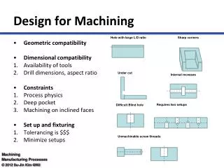
Micro-milling of thin features (ribs & webs) Tool geometry Objectives: • To study the main factors affecting the machining of thin ribs and webs. • To propose new machining strategies for micro-milling of thin ribs and webs. Conclusions: • Machining from leastsupported to best supported thin features in a component. • Machining with cutters without corner radius. • Removing the bulk of material layer by layer and then the resulting steps with ball-nose cutters at low speed. Others Material properties CATEGORY 1 “Standard” Heidenhain cycles CAD/ CAM Process conditions 2 A layer-based strategy 3 Two stage strategy Dimov, S., Pham, D.T., Ivanov, A., and Popov, K. “Micro milling strategies for machining thin features”. Proceedings of IMechE, Part C, Vol 220, no 11, 2006
Results Area 2 Area 3 Area 1 Area 4 Material Microstructure Effects in μMilling Tool geometry Experimental Set-up 3 Ultra Fine Grained (UFG) Al 5083 resulting from four Equal Channel Angular Pressing (ECAP)passes - grains of ~ 150-200 nm 1 “As Received” (AR) AI 5083 - grains of ~ 200 μm Others Material properties CATEGORY 2 Conventionally Processed (CP) Al 5083 - grains of ~ 450-600 nm CAD/ CAM Process conditions Popov, K., et al. (2006), “The effects of material microstructure in micro-milling” Proceedings of IMechE, Part B-Joint Research (Cardiff & Strathclyde)
+ +24 v 7*R3 Spindle Sensor +24 v Z V R3 C1 +24 v Tool Holder R4 _ +3 v To PLC a + Tool _ R1 R2 C Workpiece b Table New methods for tool failure detection in µMilling Tool geometry • Reflective Single-Beam Laser System (RSBLS) Others Material properties CATEGORY • Tool-Workpiece Voltage Monitoring System (TWVMS) - patented (P200701393) CAD/ CAM Process conditions • Off-line Laser System (OLS) – development of measurement routines that utilise available laser measurement systems. Gandarias, E., Dimov, S., Pham, D.T., Ivanov, A., Popov, K., Lizarralde, R., and Aráosla, P.J., (2006), “New methods for tool failure detection in micro-milling”. Proceedings of IMechE, Part B, Vol. 220, No. 2, pp 137-144
New methods for setting-up coordinate system in µMilling Tool geometry Objectives- To develop a method: • Cost-effective for setting up Machine-Workpiece Coordinate System (MWCS); • very reliable in working conditions and temperature variations; • Applicable for different tool diameters (even for diameters less than 50 µm) and spindle speed values; • Easy to follow for setting up MWCS. Experimental Results Conclusions: • By applying the proposed method it is possible to minimise uncertainties that the spindle thermal enlargement and touch probe run-outs introduce. The tests showed that the system is reliable and convenient for use. • The method does not introduce any constraints in regards to the cutting tool movements and overall part shape. • The proposed method can be applied only when conductive materials are machined. This limitation can be overcome by covering the workpiece with a thin metallic film the thickness of which is known in advance. Others Material properties CATEGORY Implementation and Validation CAD/ CAM Process conditions Popov, K., Dimov, S., Ivanov, A., Pham, D.T., Gandarias, E., (2007), “New technology for setting up the working coordinate system in micromilling”. Proceedings of International Conference, 4M2007, Whittles Publishing
Conclusions The general principles in designing machining strategies for micro features are developed, tested, and guidelines given for their correct implementation. Following these principles, new strategies are proposed to reduce the negative effects of identified factors on part quality, and at the same time to overcome some of the main problems in micro milling of “critical” thin features. The evaluated parameters - cutting speed (Vc) and feed per tooth (ft) allows better final surface roughness of the micro milled features to be achieved. The experimental results show that: • The resulting surface roughness is linearly proportional to ft; • Surface roughness is proportional to tool wear; • Proper ft could be found for longer tool life (decrease tool wear); • For micro milling (where the ratio feed per tooth/Tool Radius < 1) tool life increases as Vc increased. Unfortunately there is a machine tool and spindle limitation (60,000-120,000). Tool failure detection research has demonstrated the feasibility of three different indirect methods for detecting tool breakage during micro-milling and drilling. • The implementation of developed tool monitoring system increases significantly the process productivity, improve the precision and the quality of the machined components, and, ultimately, reduce their manufacturing costs. The mechanisms of surface improvement by refining the grain structure of metal alloys and the changes in the machining response were investigated. The results of the research carried out and reported demonstrate clearly that there is an important correlation between the isotropy/homogeneity of the material and the post process surface quality. • The different performance of the CP and ECAP samples shows that a grain refinement on its own cannot lead to significant improvements of surface integrity without reduction of material structural anisotropy.