Advances in Electrical Engineering for Physical Measurements in Condensed Matter Physics
This research explores innovative electrical engineering approaches to enhance physical measurements in condensed matter physics, particularly within solid-state physics. A tunnel-diode oscillator (TDO) model is developed for precision studies of rigid matter, allowing for the detection of phase shifts in material properties. The novel electronic circuitry enables the characterization of single-crystal materials exhibiting magnetic transitions. By implementing advanced circuit designs, frequency shifts can be accurately measured, facilitating insights into the physical and magnetic properties of various materials.

Advances in Electrical Engineering for Physical Measurements in Condensed Matter Physics
E N D
Presentation Transcript
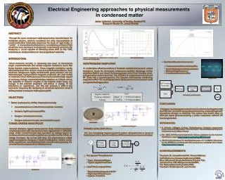
Electrical Engineering approaches to physical measurements in condensed matter Jaime Calderon, University of Turabo, Gurabo P.R. Research Mentor Dr. James Brooks • ABSTRACT: • Through the years condensed matter physics has been the basis for solid-state physics, which is considered one of its main subfields of condensed matter. Solid-state physics is the study of rigid matter or “solids”. A resonant method based on a tunnel-diode oscillator (TDO) model has been developed to study solid materials with precision. By designing a circuit capable of detecting phase shift on the TDO, scientists can study and discover new properties of materials. • INTRODUCTION: • Novel electronic circuitry is advancing new ways to characterize single crystal materials that exhibit magnetic transitions much like those found in superconductors. These magnetic transitions can be detected by electronic sensors such as tunnel diode oscillators. Such electronic designs are highly sensitive with good precision and can detect changes in physical and magnetic properties of a wide variety of materials. In fact the frequency can be measured with a high degree of accuracy. Using a resonant technique based on an LC-tank circuit, the capacitor or inductor couples to the material under study, any change in the material properties will induce a change in the inductance or capacitance, and this will produce a shift in the resonance frequency. By designing an advanced electronic circuit it will be possible to measure the frequency shift¹. • OBJECTIVES: • Detect any frequency shift by the sample on study. • Assemble a bias circuit for the tunnel diode oscillator. • Design a high frequency amplifier. • Design a waveform conversion. • Design a phase lock loop to demodulate the signal. TDO IV curve (bold red) & derivative of the IV curve transconductance (purple) Normal Diode IV curve • Oscillator Waveform Conversion • Two transistor differential amplifier. • Convert sine wave into square wave. • Works at high frequency. • Avoid transistor saturation. HIGH FREQUENCY AMPLIFIER: A combination of series and shunt feedback establishes input and output impedance, it sets the device gain and ensures stability². My design for the amplifiers MAR-6, was based on the suggested circuit from the data sheet, using simple circuit components³. The amplifier is supplied via a resistor and RF choke with a bypass capacitor. The inductor was made by hand using magnet wire #22. The coupling capacitors & inductors were chosen and made using the following equation: Square wave HP Function Generator PLL Mixer(±) Low pass Filter Waveform Conversion TDO Block diagram of the system output CONCLUSION: Finally we have designed an electronic circuit to work altogether with the TDO, this circuit will be capable of measuring and studying the RF impedance changes in materials. The system was tested using an alternate signal generator making a phase modulation with the HP function generator. MAR-6 MMIC • REFERENCES: • H. Srikanth, J Wiggins, H. Rees. “Radio-frequency impedance measurement using a tunnel-diode oscillator (TDO) technique”. Advanced Materials Research Institute, University of New Orleans. • The ARRL UHF/Microwave Experiments Manual, published by the American Radio Relay League (,http://www.arrl.org/tis/info/pdf/8702023.pdf,) • Mini-Circuits Laboratory, P.O. Box 350166, Brooklyn, NY 11235-0003. Data sheets for the MAR-6 and countless other MCL products are available at their website (http://www.minicircuits.com) TUNNEL DIODE & BIAS CIRCUIT: A tunnel diode is a type of semiconductor diode which is capable of very fast operation, well into the microwave region which is in the GHz range. Under normal forward bias operation, as voltage begins to increase, electrons tunnel through the p-n junction barrier, finally as voltage increases, the current will drop, this phenomena is called negative resistance. Using an LC-tank circuit together with the tunnel diode we will have a constant amplitude resonance by supplying the circuit with external power from the bias circuit. Amplifier circuit diagram PHASE LOCK LOOP (PLL): PLL is a closed loop frequency control system whose function is based on the phase sensitive detection of phase differences between input and output. Phase Detector Loop Filter Voltage Controlled Oscillator ACKNOWLEDGEMENTS: Thanks to Dr. James Brooks PhD, Research Mentor, Dr. Philip Kuhns, Scholarship-Scientist (NMR), Moaz Altarawneh, Graduate Student, Physics FSU, Jose Sanchez CIRL/REU personal at NHMFL, The National Science Foundation NSF, Thanks to M.I.E project, Dr. Juan Arratia. • Two types of Phase Detector • Type I, Exclusive OR gate. • Type II, digital Transistors. • Loop Filter (Low pass filter) • Required damping ratio ξ=0.707 • High natural frequency ωn • Laplace Transform. Diode Bias Circuit