Applied Systems
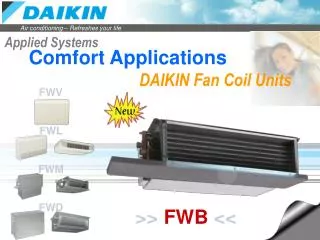
FWV FWL FWM FWD. Applied Systems. Comfort Applications. DAIKIN Fan Coil Units. >> FWB <<. Ducted Fan Coil Unit. FWB. FWM. FWD. Heating Module. Cooling Coil. Fan Module. Flexibility. Flexibility. Low Static Concealed. High Static Ducted. Medium Static Ducted. ESP = 60 to 80Pa

Applied Systems
E N D
Presentation Transcript
FWV FWL FWM FWD Applied Systems Comfort Applications DAIKIN Fan Coil Units >>FWB<<
Ducted Fan Coil Unit FWB FWM FWD Heating Module Cooling Coil Fan Module Flexibility Flexibility Low Static Concealed High Static Ducted Medium Static Ducted ESP = 60 to 80Pa Lwavg = 52dBA ESP = 100 to 120Pa Lwavg = 67dBA ESP = 20 to 40Pa Lwavg = 49dBA NRavg = 32 1,5kW 19kW • Cooling capacity from 3 to 12kW • Heating capacity from 5 to 19kW Note: Lw = Average Sound Power @ Medium Speed and free blow
Ducted Fan Coil Unit Structure Heat exchanger There is enough clearance overhead ! Heating Module Cooling Coil Fan motor assembly Fan Module H=240mm Air - filter • Modular concept • Height of the units only 240mm for all the sizes • - Cooling coil and fan module is made of: • galvanised sheet steel • internally insulated (with 3mm close-cell polyurethane) • Key-hole system for fast mounting • Rubber anti-vibration damper to isolate the unit from supporting structure • Straight duct connector is mounted to both suction and discharge side (width 30mm) • A template is available in the carton box for easy connection to the ceiling
Ducted Fan Coil Unit Structure Heat exchanger Fan motor assembly Air - filter • 3, 4 or 6 stage row cooling coil • Standard left handed water connections + air-purge (water connections can easily be turned) • Drain pan can to collect the condensate from: • * Heat exchanger • * Regulating valves
Ducted Fan Coil Unit Structure Heat exchanger Heating Module Cooling Coil Fan motor assembly Fan Module Air - filter • 1, 2 or 3 centrifugal fans with forward profile blades, • dynamically and statically balanced • - 7-speed electrical motors (with thermal protection on windings) • All 7 speeds pre-wired in the factory in the terminal block of the switch box • To reduce the requested installation space is the terminal block located on • the same side as the water connections
Ducted Fan Coil Unit Structure Heat exchanger Fan motor assembly Air - filter • Located in the air inlet • Removable from the bottom • Made of acrylic fiber, filter class EU2
Ducted Fan Coil Unit Options & accessories 4 Heating Module Cooling Coil Fan Module 2 1 3 Up to 4 units Standard factory mounted 2-way or 3-way ON/OFF-valves cooling coil + drain pan 1) Additional heat exchanger (EAH04/07/10A6) 2) Remote electronic controller (ECFWER6) 3) Master-slave interface (up to 4 FCU’s) (EPIMSA6) 4) Fan stop thermostat (YFSTA6) 5) 2-way on/off valves for additional H/E (E2MV307/310A6) 6) 3-way on/off valves for additional H/E (E2MV207/210A6) 7) Power interface (EPIA6) 5 & 6 7
Heating Module Cooling Coil Fan Module Ducted Fan Coil Unit Main Features • 9-models • 3, 4 or 6 stage row coils • Modular construction External Static Pressure 50 / 60 Pa FWB FWM FWD Low Sound Level Avg. 52dBA High perforance Air flow between 500 – 1350m³/h
Applied Systems Comfort Applications DAIKIN Fan Coil Units FWV FWL FWM FWD >>FWB<<