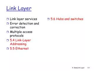
Link Layer
Link Layer. Mozafar Bag-Mohammadi University of Ilam. Contents. Overview Multiple Access Protocols Local Area Network (LAN) Ethernet Hubs, Bridges, and Switches PPP: The Point-to-Point Protocol Physical Layer and Link Layer Technology. 1. Overview: Link Layer. M. H. H. H. H. H. H.

Link Layer
E N D
Presentation Transcript
Link Layer Mozafar Bag-Mohammadi University of Ilam
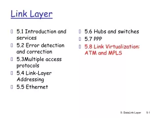
Contents • Overview • Multiple Access Protocols • Local Area Network (LAN) • Ethernet • Hubs, Bridges, and Switches • PPP: The Point-to-Point Protocol • Physical Layer and Link Layer Technology
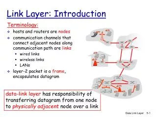
M H H H H H H H H H t t n l l n n t t M M application transport network link physical M • Communication service between two physically connected devices: • host-router, router-router, host-host • unit of data: frame network link physical data link protocol M frame phys. link adapter card
1.1 Link Layer Services • Framing, link access: • encapsulate datagram into frame, adding header, trailer • implement channel access if shared medium, • ‘physical addresses’ used in frame headers to identify source, dest • different from IP address! • Reliable delivery between two physically connected devices: • seldom used on low bit error link (fiber, some twisted pair) • wireless links: high error rates • Q: why both link-level and end-end reliability?
1.1 Link Layer Services (more) • Flow Control: • pacing between sender and receivers • Error Detection: • errors caused by signal attenuation, noise. • receiver detects presence of errors: • signals sender for retransmission or drops frame • Error Correction: • receiver identifies and corrects bit error(s) without resorting to retransmission
M H H H H H H H H H t n l t t n l t n M M application transport network link physical M 1.2 Link Layer: Implementation • implemented in “adapter” • e.g., PCMCIA card, Ethernet card • typically includes: RAM, DSP chips, host bus interface, and link interface network link physical data link protocol M frame phys. link adapter card
Error Detection • To send extra information to find error in the frame. • The simplest form is sending two copies, • inefficient. • Sending the sum of values (?) in the frame, checksum. • In Internet, consider 16 bits sequences and then use one-complement to find the result. • Sending parity, odd or even parity. • Two dimensional parity, adding one extra bit, parity bit, to code and also find the parity for each bit position for total data.
Internet Checksum Algorithm • View message as a sequence of 16-bit integers; sum using 16-bit ones-complement arithmetic; take ones-complement of the result. u_short cksum(u_short *buf, int count) { register u_long sum = 0; while (count--) { sum += *buf++; if (sum & 0xFFFF0000) { /* carry occurred, so wrap around */ sum &= 0xFFFF; sum++; } } return ~(sum & 0xFFFF); }
Cyclic Redundancy Code (CRC) • Add k bits of redundant data to an n-bit message • Where k << n • e.g., k = 32 and n = 12,000 (1500 bytes) T R M m MSB i.e. T = M.2r + R Modulo-2 addition (XOR)
CRC(cont) • Represent n-bit message as n-1 degree polynomial • e.g., MSG=10011010 as M(x) = x7 + x4 + x3 + x1 • Let k be the degree of some divisor polynomial • e.g., C(x) = x3 + x2 + 1 • Transmit polynomial T(x) that is evenly divisible by C(x) • shift left k bits, i.e., M(x)xk • subtract remainder of M(x)xk / C(x) from M(x)xk
CRC (cont) • Receiver polynomial T(x) + E(x) • E(x) = 0 implies no errors • Divide (T(x) + E(x)) by C(x); remainder zero if: • E(x) was zero (no error), or • E(x) is exactly divisible by C(x) • All operation is done in modulo 2 in which there is no carry. Then, the operation can be done by XOR only.
CRC(cont) Example: M(x)= 110101, C(x) = 1001 1 0 0 1 1 1 0 1 0 1 0 0 0 1 0 0 1 1 0 0 0 1 0 0 1 0 0 1 1 0 0 0 0 0 1 1 0 0 0 0 0 1 1 0 0 1 0 0 1 1 0 1 0 1 0 0 1 0 1 1 The final transmitted message is: T(x) = 1 1 0 1 0 10 1 1 R
Selecting C(x) • All single-bit errors, as long as the xk and x0 terms have non-zero coefficients. • All double-bit errors, as long as C(x) contains a factor with at least three terms • Any odd number of errors, as long as C(x) contains the factor (x + 1) • Any ‘burst’ error (i.e., sequence of consecutive error bits) for which the length of the burst is less than k bits. • Most burst errors of larger than k bits can also be detected • See Table 2.6 on page 102 for common C(x)
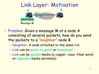
2. Multiple Access Links and Protocols 2.1 Three types of “links”: • point-to-point (single wire, e.g. PPP, SLIP) • broadcast (shared wire or medium; e.g, Ethernet, Wavelan, etc.) • switched (e.g., switched Ethernet, ATM etc)
2.2 Multiple Access protocols • single shared communication channel • two or more simultaneous transmissions by nodes: interference • only one node can send successfully at a time • multiple access protocol: • distributed algorithm that determines how stations share channel, i.e., determine when station can transmit • communication about channel sharing must use channel itself! • type of protocols: • synchronous or asynchronous • information needed about other stations • robustness (e.g., to channel errors) • performance
2.3 Multiple Access Control Protocols Three broad classes: • Channel Partitioning • divide channel into smaller “pieces” (time slots, frequency, code) • allocate piece to node for exclusive use • TDMA, FDMA, CDMA • Random Access • allow collisions • “recover” from collisions • CSMA, ALOHA • Taking turns • tightly coordinate shared access to avoid collisions • Token ring Goal: efficient, fair, simple, decentralized
2.4 Random Access protocols • When node has packet to send • transmit at full channel data rate R. • no a priori coordination among nodes • two or more transmitting nodes -> “collision”, • random access MAC protocol specifies: • how to detect collisions • how to recover from collisions (e.g., via delayed retransmissions) • Examples of random access MAC protocols: • slotted ALOHA • ALOHA • CSMA and CSMA/CD
2.5 CSMA: Carrier Sense Multiple Access CSMA: listen before transmit: • If channel sensed idle: transmit entire pkt • If channel sensed busy, defer transmission • human analogy: don’t interrupt others!
2.6 CSMA/CD (Collision Detection) CSMA/CD: carrier sensing, deferral as in CSMA • collisions detected within short time • colliding transmissions aborted, reducing channel wastage • persistent or non-persistent retransmission • collision detection: • easy in wired LANs: measure signal strengths, compare transmitted, received signals • difficult in wireless LANs: receiver shut off while transmitting • human analogy: the polite conversationalist
Collisions A B A B A B A B
3. Local Area Network (LAN) • addressing • Ethernet • hubs, bridges, switches • 802.11 • PPP • ATM
3.2 LAN Address (more) • MAC address allocation administered by IEEE • manufacturer buys portion of MAC address space (to assure uniqueness) • Analogy: (a) MAC address: like Social Security Number (b) IP address: like postal address • MAC flat address => portability • can move LAN card from one LAN to another • IP hierarchical address NOT portable • depends on network to which one attaches
IEEE 802 Standards • IEEE 802 is a family of standards for LANs, which defines an LLC and several MAC sublayers
4. Ethernet “dominant” LAN technology: • cheap $200 for 1Gbps Ethernet • first widely used LAN technology • Simpler, cheaper than token LANs and ATM • Kept up with speed race: 10Mbps, 100Mbps, 1Gbps, 10Gbps Metcalfe’s Ethernet sketch
Ethernet • Speed: 10Mbps -10 Gbps • Standard: 802.3, Ethernet II (DIX) • Most popular physical layers for Ethernet: • 10Base5 Thick Ethernet: 10 Mbps coax cable • 10Base2 Thin Ethernet: 10 Mbps coax cable • 10Base-T 10 Mbps Twisted Pair • 100Base-TX100 Mbps over Category 5 twisted pair • 100Base-FX100 Mbps over Fiber Optics • 1000Base-FX 1Gbps over Fiber Optics • 10000Base-FX 10Gbps over Fiber Optics (for wide area links)
Bus Topology • 10Base5 and 10Base2 Ethernets has a bus topology
Star Topology • Starting with 10Base-T, stations are connected to a hub in a star configuration
4.1 Ethernet uses CSMA/CD A: sense channel, if idle then { transmit and monitor the channel; If detect another transmission then { abort and send jam signal; update # collisions; delay as required by exponential backoff algorithm; goto A } else {done with the frame; set collisions to zero} } else {wait until ongoing transmission is over and goto A}
4.1 Ethernet’s CSMA/CD (more) Jam Signal: make sure all other transmitters are aware of collision; 48 bits; Exponential Backoff: • Goal: adapt retransmission attempts to estimated current load • heavy load: random wait will be longer • first collision: choose K from {0,1}; delay is K x 512 bit transmission times • after second collision: choose K from {0,1,2,3}… • after ten or more collisions, choose K from {0,1,2,3,4,…,1023}
64 48 48 16 32 Src Dest Preamble Type Body CRC addr addr Frame format
Bits 0 0 1 0 1 1 1 1 0 1 0 0 0 0 1 0 NRZ Encoding • Encode binary data onto signals • Bits flow is between network adaptors. • How to send clock information? • Extract from signals or data. • The simplest way is 0 as low signal and 1 as high signal. This is known as Non-Return to zero (NRZ)
Problem with NRZ • Consecutive 0’s or 1’s may create problems. • Synchronization problem because of difference in the sender or receiver clocks. • The average of signals which is used to distinguish between low or high may move and make the decoding difficult. This is called baseline wander • Unable to recover clock
Alternative Encodings • Non-return to Zero Inverted (NRZI) • make a transition from current signal to encode a 1; stay at current signal to encode a zero • solves the problem of consecutive 1s • Manchester encoding • transmit XOR of the NRZ encoded data and the clock. • 0 is being encoded as a low to high transition and 1 as high to low. • It doubles the rate, then, it is only 50% efficient. • The rate signal changing is called baud rate.
Bits 0 0 1 0 1 1 1 1 0 1 0 0 0 0 1 0 NRZ Clock Manchester NRZI Encodings (cont)
Encodings (cont) • 4B/5B: The idea is insert extra bits to break the consecutive bit patterns. • every 4 bits of data encoded in a 5-bit code • 5-bit codes selected to have no more than one leading 0 and no more than two trailing 0s • thus, never get more than three consecutive 0s • resulting 5-bit codes are transmitted using NRZI • achieves 80% efficiency. • Unused code are used for control. I.e. 11111 is for line is idle or 00000 for the line is dead. • FDDI is using this scheme.
Bits Node A Adaptor Adaptor Node B Frames Framing • How to distinguish between data and garbage. • Break sequence of bits into a frame • Typically implemented by network adaptor
8 16 16 8 Beginning Ending Header Body CRC sequence sequence Byte-oriented Approaches • Sentinel-based • delineate frame with special pattern: 01111110 or STX, ETX, etc characters. • e.g., HDLC, SDLC, PPP • problem: special pattern or characters appear in the payload • solution: bit stuffing • sender: insert 0 after five consecutive 1s • receiver: delete 0 that follows five consecutive 1s
Byte-oriented Approaches (cont) • Counter-based • include payload length in the header • e.g., DDCMP protocol from DEC. • problem: count field corrupted • solution: catch when CRC fails
Bit-oriented Approaches • Clock-based • each frame is 125us long • e.g., SONET: Synchronous Optical Network • STS-n (STS-1 = 51.84 Mbps)
Stop-and-Wait Sender Receiver • Problem: keeping the pipe full • Example • 1.5Mbps link x 45ms RTT = 67.5Kb (8KB) • 1KB frames imples 1/8th link utilization
Sender Receiver … ime T … Sliding Window • Allow multiple outstanding (un-ACKed) frames • Upper bound on un-ACKed frames, called window
£ SWS … … LAR LFS SW: Sender • Assign sequence number to each frame (SeqNum) • Maintain three state variables: • send window size (SWS) • last acknowledgment received (LAR) • last frame sent (LFS) • Maintain invariant: LFS - LAR <= SWS • Advance LAR when ACK arrives • Buffer up to SWS frames
£ RWS … … LFR LFA SW: Receiver • Maintain three state variables • receive window size (RWS) • largest frame acceptable (LFA) • last frame received (LFR) • Maintain invariant: LFA - LFR <= RWS • Frame SeqNum arrives: • if LFR < SeqNum < = LFA accept • if SeqNum < = LFR or SeqNum > LFA discarded • Send cumulative ACKs
Sequence Number Space • SeqNum field is finite; sequence numbers wrap around • Sequence number space must be larger then number of outstanding frames • SWS <= MaxSeqNum-1 is not sufficient • suppose 3-bit SeqNum field (0..7) • SWS=RWS=7 • sender transmit frames 0..6 • arrive successfully, but ACKs lost • sender retransmits 0..6 • receiver expecting 7, 0..5, but receives second incarnation of 0..5 • SWS < (MaxSeqNum+1)/2 is correct rule • Intuitively, SeqNum “slides” between two halves of sequence number space
Concurrent Logical Channels • Multiplex 8 logical channels over a single link • Run stop-and-wait on each logical channel • Maintain three state bits per channel • channel busy • current sequence number out • next sequence number in • Header: 3-bit channel num, 1-bit sequence num • 4-bits total • same as sliding window protocol • Separates reliability from order
5. 1 Interconnecting LANs 5. Hubs, Bridges and Switches Q: Why not just one big LAN? • Limited amount of supportable traffic: on single LAN, all stations must share bandwidth • limited length: 802.3 specifies maximum cable length • large “collision domain” (can collide with many stations)
Ethernet Hubs vs. Ethernet Switches • An Ethernet switch is a packet switch for Ethernet frames • Buffering of frames prevents collisions. • Each port is isolated and builds its own collision domain • An Ethernet Hub does not perform buffering: • Collisions occur if two frames arrive at the same time. Hub Switch