Dr. Mozafar Bag-Mohammadi: Link Layer Communication Overview
Learn about error detection, encoding, framing, acknowledgments, and timeouts in link layer communication services. Understand the implementation, error detection methods like checksum, and Cyclic Redundancy Code (CRC). Discover encoding techniques like NRZ, NRZI, and Manchester encoding for reliable data transmission.

Dr. Mozafar Bag-Mohammadi: Link Layer Communication Overview
E N D
Presentation Transcript
Link Layer Dr. Mozafar Bag-Mohammadi University of Ilam
Contents • Overview • Error detection • Encoding • Framing • Acknowledgements & Timeouts
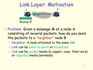
Communication service between two physically connected devices: host-router, router-router, host-host unit of data: frame M H H H H H H H H H t n l t t t n l n M M application transport network link physical M Link layer network link physical data link protocol M frame phys. link adapter card
Link Layer Services • Framing, link access: • encapsulate datagram into frame, adding header, trailer • implement channel access if shared medium, • ‘physical addresses’ used in frame headers to identify source, dest • different from IP address! • Reliable delivery between two physically connected devices: • seldom used on low bit error link (fiber, some twisted pair) • wireless links: high error rates
1.1 Link Layer Services (more) • Flow Control: • pacing between sender and receivers • Error Detection: • errors caused by signal attenuation, noise. • receiver detects presence of errors: • signals sender for retransmission or drops frame • Error Correction: • receiver identifies and corrects bit error(s) without resorting to retransmission
M H H H H H H H H H t n l t t n l t n M M application transport network link physical M 1.2 Link Layer: Implementation • implemented in “adapter” • e.g., PCMCIA card, Ethernet card • typically includes: RAM, DSP chips, host bus interface, and link interface network link physical data link protocol M frame phys. link adapter card
2.Error Detection • To send extra information to find error in the frame. • The simplest form is sending two copies, • inefficient. • Sending the sum of values (?) in the frame, checksum. • In Internet, consider 16 bits sequences and then use one-complement to find the result. • Sending parity, odd or even parity. • Two dimensional parity, adding one extra bit, parity bit, to code and also find the parity for each bit position for total data.
Internet Checksum Algorithm • View message as a sequence of 16-bit integers; sum using 16-bit ones-complement arithmetic; take ones-complement of the result. u_short cksum(u_short *buf, int count) { register u_long sum = 0; while (count--) { sum += *buf++; if (sum & 0xFFFF0000) { /* carry occurred, so wrap around */ sum &= 0xFFFF; sum++; } } return ~(sum & 0xFFFF); }
Cyclic Redundancy Code (CRC) • Add k bits of redundant data to an n-bit message • Where k << n • e.g., k = 32 and n = 12,000 (1500 bytes) T R M m MSB i.e. T = M.2k + R Modulo-2 addition (XOR)
CRC(cont) • Represent n-bit message as n-1 degree polynomial • e.g., MSG=10011010 as M(x) = x7 + x4 + x3 + x1 • Let k be the degree of some divisor polynomial • e.g., C(x) = x3 + x2 + 1 • Transmit polynomial T(x) that is evenly divisible by C(x) • shift left k bits, i.e., M(x)xk • subtract remainder of M(x)xk / C(x) from M(x)xk
CRC (cont) • Receiver polynomial T(x) + E(x) • E(x) = 0 implies no errors • Divide (T(x) + E(x)) by C(x); remainder zero if: • E(x) was zero (no error), or • E(x) is exactly divisible by C(x) • All operation is done in modulo 2 in which there is no carry. Then, the operation can be done by XOR only.
CRC(cont) Example: M(x)= 110101, C(x) = 1001 1 0 0 1 1 1 0 1 0 1 0 0 0 1 0 0 1 1 0 0 0 1 0 0 1 0 0 1 1 0 0 0 0 0 1 1 0 0 0 0 0 1 1 0 0 1 0 0 1 1 0 1 0 1 0 0 1 0 1 1 The final transmitted message is: T(x) = 1 1 0 1 0 10 1 1 R
Selecting C(x) • All single-bit errors, as long as the xk and x0 terms have non-zero coefficients. • All double-bit errors, as long as C(x) contains a factor with at least three terms • Any odd number of errors, as long as C(x) contains the factor (x + 1) • Any ‘burst’ error (i.e., sequence of consecutive error bits) for which the length of the burst is less than k bits. • Most burst errors of larger than k bits can also be detected • See Table 2.6 on page 102 for common C(x)
Bits 0 0 1 0 1 1 1 1 0 1 0 0 0 0 1 0 NRZ 3.Encoding • Encode binary data onto signals • Bits flow is between network adaptors. • How to send clock information? • Extract from signals or data. • The simplest way is 0 as low signal and 1 as high signal. This is known as Non-Return to zero (NRZ)
Problem with NRZ • Consecutive 0’s or 1’s may create problems. • Synchronization problem because of difference in the sender or receiver clocks. • The average of signals which is used to distinguish between low or high may move and make the decoding difficult. This is called baseline wander • Unable to recover clock
Alternative Encodings • Non-return to Zero Inverted (NRZI) • make a transition from current signal to encode a 1; stay at current signal to encode a zero • solves the problem of consecutive 1s • Manchester encoding • transmit XOR of the NRZ encoded data and the clock. • 0 is being encoded as a low to high transition and 1 as high to low. • It doubles the rate, then, it is only 50% efficient. • The rate signal changing is called baud rate.
Bits 0 0 1 0 1 1 1 1 0 1 0 0 0 0 1 0 NRZ Clock Manchester NRZI Encodings (cont)
Encodings (cont) • 4B/5B: The idea is insert extra bits to break the consecutive bit patterns. • every 4 bits of data encoded in a 5-bit code • 5-bit codes selected to have no more than one leading 0 and no more than two trailing 0s • thus, never get more than three consecutive 0s • resulting 5-bit codes are transmitted using NRZI • achieves 80% efficiency. • Unused code are used for control. I.e. 11111 is for line is idle or 00000 for the line is dead. • FDDI is using this scheme.
Bits Node A Adaptor Adaptor Node B Frames 4.Framing • How to distinguish between data and garbage. • Break sequence of bits into a frame • Typically implemented by network adaptor
8 16 16 8 Beginning Ending Header Body CRC sequence sequence Byte-oriented Approaches • Sentinel-based • delineate frame with special pattern: 01111110 or STX, ETX, etc characters. • e.g., HDLC, SDLC, PPP • problem: special pattern or characters appear in the payload • solution: • bit stuffing • sender: insert 0 after five consecutive 1s • receiver: delete 0 that follows five consecutive 1s • Byte stuffing
Byte-oriented Approaches (cont) • Counter-based • include payload length in the header • e.g., DDCMP protocol from DEC. • problem: count field corrupted • solution: catch when CRC fails
Stop-and-Wait Sender Receiver • Problem: keeping the pipe full • Example • 1.5Mbps link x 45ms RTT = 67.5Kb (8KB) • 1KB frames imples 1/8th link utilization
Sender Receiver … ime T … Sliding Window • Allow multiple outstanding (un-ACKed) frames • Upper bound on un-ACKed frames, called window
£ SWS … … LAR LFS SW: Sender • Assign sequence number to each frame (SeqNum) • Maintain three state variables: • send window size (SWS) • last acknowledgment received (LAR) • last frame sent (LFS) • Maintain invariant: LFS - LAR <= SWS • Advance LAR when ACK arrives • Buffer up to SWS frames
£ RWS … … LFR LFA SW: Receiver • Maintain three state variables • receive window size (RWS) • largest frame acceptable (LFA) • last frame received (LFR) • Maintain invariant: LFA - LFR <= RWS • Frame SeqNum arrives: • if LFR < SeqNum < = LFA accept • if SeqNum < = LFR or SeqNum > LFA discarded • Send cumulative ACKs
Sequence Number Space • SeqNum field is finite; sequence numbers wrap around • Sequence number space must be larger then number of outstanding frames • SWS <= MaxSeqNum-1 is not sufficient • suppose 3-bit SeqNum field (0..7) • SWS=RWS=7 • sender transmit frames 0..6 • arrive successfully, but ACKs lost • sender retransmits 0..6 • receiver expecting 7, 0..5, but receives second incarnation of 0..5 • SWS < (MaxSeqNum+1)/2 is correct rule • Intuitively, SeqNum “slides” between two halves of sequence number space
Concurrent Logical Channels • Multiplex 8 logical channels over a single link • Run stop-and-wait on each logical channel • Maintain three state bits per channel • channel busy • current sequence number out • next sequence number in • Header: 3-bit channel num, 1-bit sequence num • 4-bits total • same as sliding window protocol • Separates reliability from order