Download
1 / 34
340 likes | 368 Views
This document provides an in-depth overview of the engineering aspects of the NCSX project, covering design requirements, solutions, risk assessment, cost estimation, critical activities, and conclusions. It delves into key aspects such as General Requirements Document (GRD), reference scenarios, coil structures, vacuum vessel, and safety measures. The text outlines design concepts, analysis of stellarator core, vacuum systems, diagnostics, electrical power, cooling, cryogenics, and safety protocols, emphasizing adherence to ISM principles and environmental responsibility. Major risks and mitigation strategies are also discussed.

E N D
NCSX Engineering Overview Wayne Reiersen NCSX Engineering Manager On behalf of the NCSX Team 1
Engineering Overview • Design requirements • Design solutions • Risk assessment and mitigation • Cost and schedule methodologies • Total estimated cost (TEC) • Critical path activities • Conclusions 2
General Requirements Document (GRD) • The primary handshake between Physics and Engineering • Key requirements include reference scenarios, flexibility, heating power, repetition rate, wall conditioning, diagnostics, and safety • Formal review, approval, and placement under change control scheduled for the end of Conceptual Design • The top-level specification for NCSX - provides the basis for lower level specifications 3
Reference Scenarios • Define plasma and coil currents versus time • Provide substantial dynamic flexibility in plasma current, toroidal field, beta, and pulse length • Pulse length. Example: The 1.7T High Beta Scenario has a 0.3s flattop. At 1.2T, the flattop grows to 1.7s. • Flexibility. Example: All flexibility requirements in the GRD can be met with the coils systems designed for the reference scenarios. • TF, PF, and modular coil systems and VV designed for all reference scenarios • Electrical power systems designed for the Initial Ohmic Scenario (ample for ohmic and initial NB experiments) and upgradeable for all other reference scenarios. 4
Coil Support Structure Vacuum Vessel Modular Coils TF Coil A conceptual design has been developed that meets performance requirements 6
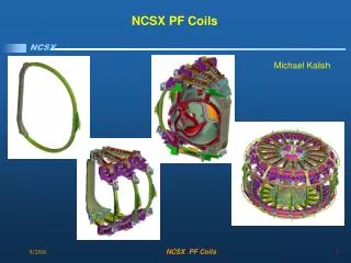
A conceptual design has been developed that meets performance requirements PF Coils Base Structure 7
A conceptual design has been developed that meets performance requirements Cryostat 8
Analysis of stellarator core • Current waveforms, temperature profiles, and power supply requirements generated for reference scenarios • Field and force calculations performed, worst case loads identified • Structural analysis of coil systems was very encouraging – no fundamental problem areas are seen • The vacuum vessel looks to be structurally robust under atmospheric and disruption (350kA) loads. The electrical time constant is 5ms, well below the upper limit of 10ms. • R&D is planned to develop material properties of copper-glass-epoxy composite winding pack in modular coils and establish static and fatigue allowables • More details provided in the following talk (Nelson) 9
Vacuum Pumping (22) Re-use existing PBX-M TMPs and backing pumps Gas Fueling (23) Re-use existing PBX-M equipment NBI (25) Re-use PBX-M beamlines Diagnostics (3) Build new diagnostics, adapt/extend designs developed for NSTX Central I&C (5) Pattern closely after NSTX Electrical Power (4) Share D-Site PS with NSTX for modular, TF, and PF coils. Use C-Site AC power system for other loads Water Cooling (62) Add cooling loops as required. Tie into C-Site water system. Cryogenics (63) Truck in LN2 for cryo cooling Helium Bakeout (65) Use NSTX bakeout system design Design concepts in other subsystems draw on existing equipment and designs 10
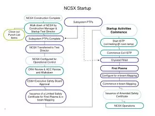
All NCSX activities will be conducted using the principles and core functions of ISM 11
NCSX will be constructed and operated safely and in an environmentally responsible way • Safety requirements of the PPPL ES&H Manual and PPPL policies and procedures will be applied. • An Environmental Evaluation Notification Form (EENF) and a Preliminary Hazards Analysis (PHA) have been prepared – design requirements will be captured in the GRD and flowed down to lower level specifications • Preparation of An Environmental Assessment (EA) is planned • Line management is responsible for safety - ES&H professionals will provide support in document and design reviews and as members of the Change Control Board (CCB) • NCSX will be constructed at PPPL using procedures and practices that are familiar to technicians and supported by management. Hazard controls include: work planning; installation, test, and operating procedures; design reviews; job hazard analyses; pre- and post-job briefings; protective equipment; and worker training. • A Safety Assessment Document (SAD) will be prepared and a readiness assessment conducted by PPPL/DOE personnel prior to first plasma 12
Major Risks • Two major risks identified • Providing unacceptable surface quality due to field errors introduced in the design and construction of NCSX • Not meeting technical, cost, and schedule objectives in the fabrication of the modular coils and vacuum vessel • Other stellarator core components are straightforward to design and build, and carry much less risk • Ancillary systems, which are largely based on re-use of existing equipment or built with commercial, off-the-shelf equipment (COTS), carry much less risk 13
Mitigating risks due to field errors • Stringent requirement specified in the GRD • The toroidal flux in island regions due to fabrication errors, magnetic materials, or eddy currents shall not exceed 10% of the total toroidal flux in the plasma • Potential sources of field error were minimized wherever possible • ±1.5mm (~0.1%) was imposed as the preliminary requirement for the position of the current centroid • Consistent with historical precedent • Sensitivity studies are being performed to understand which coil perturbations and resonances are most critical, in order to guide the establishment of fabrication and assembly tolerances • Trim coils are being designed to suppress significant islands that might be left 14
Minimizing sources of field errors (1) • Islands in the reference plasma were eliminated through tailoring of the winding geometry • Stellarator symmetry has been strictly preserved • Magnetic materials (including the weld regions) have been strictly avoided • Eddy currents in surrounding structures minimized through the use of thin, high resistivity materials (VV) and electrical breaks (modular coils) 15
Good Bad Minimizing sources of field errors (2) • Displacements under load minimized through continuous structural support of the winding on a stiff, toroidal shell • State-of-the-art measurement techniques will be used in coil fabrication and assembly • “Opposing double layer” winding scheme proposed for all coils to minimize field errors from transitions • Coaxial (or multi-filament) leads used 16
Minimizing sources of field errors (3) • Build-up of tolerances minimized in the design • Modular coils are wound on a machined surface on the modular coil winding form, which also serves as the support structure, and never removed • Finished modular coils are individually positioned to minimize field errors – the position of any coil is independent of its neighbor, avoiding tolerance build-up 17
Sensitivity studies of construction errors • ±1.5mm distortions (3 directions, m=0,1,…6) and displacements (6 DOF) in modular, TF, and PF coils were studied • n/m=1/2 was the most dangerous mode due to perturbations in a single modular coil, but is effectively suppressed using external trim coils 18
Non-symmetric (n/m=1/2) islands from worst case distortion/displacement (1 coil) suppressed with external trim coils Max current of 63 kAT in external trim coils 16.5% total island size 1.3% total island size
Symmetric islands (n/m=3/5,3/6) from systematicworst case distortion (6 coils) suppressed with internal trim coils 179 AT max coil current in internal trim coils 13.4% total island size 5.1% total island size (primarily 6/10)
Construction errors in TF and PF coils are more benign than in modular coils Looser tolerances in TF and PF coils may be OK 21
NCSX will pursue a “belt and suspenders” approach to minimize field errors due to construction errors • Our goal is to • establish a cost-effective set of tolerance requirements to minimize island size • optimize the design of trim coils to surgically eliminate islands • The preliminary tolerance requirement of ±1.5mm on the current center looks “reasonable” • Additional sensitivity studies will identify where tolerances should be loosened or tightened – get more performance with no increase in cost • Trim coils work well and will be optimized to eliminate coupling to non-targeted modes 22
Procurement plans structured to mitigate risk • Not meeting technical, cost, and schedule objectives in the fabrication of the modular coils and vacuum vessel is the 2nd major risk • Vacuum vessel. Highly shaped vacuum vessel poses design challenges similar to those encountered on HSX and W-7AS • Modular coils. Large, highly shaped castings with precision machining required. • Multi-stage procurements planned to mitigate this risk • Concurrent engineering folds manufacturing considerations into the design • Vendors demonstrate mfg capability with full-scale prototypes • Competitive environment maintained by carrying multiple vendors • Winding and VPI of modular coils will be performed at PPPL • Increases pool of suppliers for casting/machining (better quality, lower cost) • Shortens schedule by ~8 months • Reduces risks associated with quality and schedule 23
Cost and Schedule Basis • Vendor Cost Inputs. Inputs were received from industry in the manufacturing studies of the modular coils and vacuum vessel. Separate vendor inputs were received for other components, such as the TF and PF coils and coil support structure. • NSTX experience. Recent procurements and work on NSTX for similar systems (particularly the Central Instrumentation and Control System, Electrical Power Systems, Helium Bakeout System, and Diagnostic Systems) provided valuable, detailed cost and schedule information. • PBX-M experience. Past work on PBX-M provided a basis for estimating labor hours for refurbishing and reinstalling PBX-M equipment, such as the Neutral Beam System and Torus Vacuum Pumping System. 25
Developing the Resource-Loaded Schedule • The cost and schedule estimates were developed by cognizant WBS Managers and integrated using the Primavera database and scheduling software. • Labor was input in hours and the non-labor (e.g., M&S, travel, etc.) was input in direct dollars. • A PPPL-specific MHX G&A rate was applied since the majority of procurements will be handled by PPPL Procurement • ORNL and PPPL provided labor rates by labor type and the projected escalation factors to be used. This information was input into the Primavera database so appropriate rates and escalation could be applied by year of expenditure. • Linkages between tasks were input and the critical path as identified. Resources were shifted where possible to achieve a spending profile that approximated the overall DOE guidance. 26
Estimating Contingency • A standardized approach for developing contingency was utilized. • The contingency estimate was developed by assessing risks and assigning weighting factors in three areas: technical, cost, and schedule. • This approach has been utilized on major DOE construction projects and, most recently at PPPL, on NSTX. 27
Total Estimated Cost (TEC) is $72M • The Total Estimated Cost (TEC) is$72M in year-of-expenditure dollars • The contingency of $15.7M is 28% of the TEC (before contingency). • The dominant cost element, representing half (49%) of the TEC (before contingency), is the Stellarator Core (WBS 1), which costs $27.3M. • Within the Stellarator Core, the Modular Coils (WBS 17) is the single largest cost element at $16.2M, or 59% of the cost of the Stellarator Core. • One reason the Stellarator Core is such a large fraction of the TEC is due to the many assets at PPPL that are being re-used in the ancillary systems and facilities – the replacement cost of site credits (e.g., neutral beams, power supplies, and the experimental complex) would be comparable to the $72M TEC. 28
Critical Path Schedule • Modular coil design (Title I and II) and manufacturing R&D must be completed in FY03 • Production of the cast and machined winding forms is on the critical path until the last one is delivered – need to get started ASAP • Winding the modular coils and assembling the 3rd field period then become critical – winding the coils and assembling the third field period at PPPL provides schedule contingency with the option for a 2nd shift • Installing the 3rd field period in the NCSX Test Cell and successfully pumping down the device comes next • Almost four (4) months of schedule contingency is provided between pumpdown and power testing 30
Conclusions The likelihood of the project meeting its technical mission is excellent • An experienced, multi-institutional design team has been assembled. • Requirements have been developed and documented • A robust design has been developed • Manufacturability and constructability have been enhanced by involving industry in the conceptual design of developmental components (modular coils and vacuum vessel) and planning extensive manufacturing R&D for preliminary and final design to mitigate technical risks • Design features have been incorporated in the stellarator core to facilitate assembly. Ample facilities for assembly have been provided. • Major risks have been identified. Mitigation plans are in place. 32
Conclusions Cost and schedule estimates, including contingencies, have a strong and defensible basis • Cost and schedule estimates for stellarator core elements are bottoms-up estimates with extensive input from industry • Cost and schedule estimates for other elements benefit from recent, similar experience on NSTX (Central I&C, Electrical Power, and Diagnostics) and past experience on PBX-M (e.g., NBI, Vacuum Pumping, and Gas Fueling) • Cost contingencies have been estimated based on systematic consideration of technical, cost and schedule risks and appear reasonable • Schedule contingency has been provided with a four month slack period preceding first plasma and by winding the modular coils and assembling the field periods in-house. • The critical path has been clearly identified and is driving project priorities 33
Conclusions Management plans and procedures that have been proven to work on TFTR D&D and NSTX, provide high confidence that the project will be executed smoothly and safely • The NCSX Project Execution Plan (PEP) provides the framework for project participants to work as an integrated team • The resource loaded schedule provides the basis for work authorization. Open jobs will be tracked on a monthly basis to ensure that cost and schedule variances are identified and remedied early. • NCSX will be constructed and operated at PPPL safely and environmentally responsible way, applying PPPL procedures and practices that are built on ISM guiding principles and core functions, familiar to technicians, and supported by management. 34