NCSX
NCSX. NCSX Vacuum Vessel Heat Balance Analysis P Goranson 3/10/04. GOAL. DETERMINE: HEAT LOSSES THROUGH INSULATION CRYOGENIC AND ELECTRICAL POWER REQUIREMENTS VIABILITY OF HEAT TRACING. REQUIREMENTS/CRITERIA. VV baked at 350 C & maintained 20 C during standby operation

NCSX
E N D
Presentation Transcript
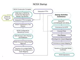
NCSX NCSX Vacuum Vessel Heat Balance Analysis P Goranson 3/10/04
GOAL DETERMINE: • HEAT LOSSES THROUGH INSULATION • CRYOGENIC AND ELECTRICAL POWER REQUIREMENTS • VIABILITY OF HEAT TRACING
REQUIREMENTS/CRITERIA • VV baked at 350 C & maintained 20 C during standby operation • During bakeout, port extensions maintained at 150 C at the flanges ends and 350 C at VV end • Cryostat and modular coils maintained at 80 K during both bakeout and standby operation
ASSUMPTIONS • Cryostat Exterior Temperature 288 K • Cryostat radius 123“, height 119" • Vessel area, excluding ports 52200 in2 • Port standpipe area 65000 in2 • Coil area facing vessel 23400 in2
PROPERTIES • Insulation conductivity = 0.0002 W/cm-K • An efficiency factor of 75% is assumed
Vessel microtherm Cryo foam Backfill insul. Port insul. Path to coil Port cover thickness(cm) thickness(cm) effec. thick.(cm) thickness(cm) (cm) (cm) Bake 1.27 20.0 15.0 2.54 8.00 1.27 2 20.0 15.0 5.1 8.00 2.00 2.54 20.0 15.0 5.1 8.00 2.54 Idle 1.27 20.0 15.0 2.54 8.00 1.27 2 20.0 15.0 5.1 8.00 2.00 2.54 20.0 15.0 5.1 8.00 2.54 INSULATION THICKNESS
METHODOLOGY • Analysis done as spreadsheet in MICROSOFT EXCEL • Vessel and ports represented as simple areas conducting heat across insulating layers to constant temperature heat sinks. • Input variables - insulation thicknesses - conductivity - vessel temperatures - surface areas. • Outputs - heat loss from vessel body - heat gain to cryostat and coils • Port heating balance - finite differences; iterated until boundary conditions [temperatures] met. - outputs are conduction loss and electrical heating input - values of typical port converted to surface flux; used to estimate totals for all ports.
Vessel Port Cover Vessel to coil Vessel to Cryo Cryo inleak Vessel to Coil to ambient sides Port to Cryo Vessel Coolant Qt Qv front Qc Qa Qci Qp Qn kW kW kW kW kW kW kW Bake 0.3 3.3 17.2 1.9 2.7 19.5 -30.02 0.3 3.3 10.9 1.2 2.7 9.75 -19.13 0.3 3.3 8.6 1.0 2.7 9.75 -16.54 Idle 0.1 3.3 6.8 0.0 1.1 9.4 -8.06 0.1 3.3 4.3 0.0 1.1 4.7 -5.55 0.1 3.3 3.4 0.0 1.1 4.7 -4.63 RESULTS - VV HEAT LOSSES
Qh Total Total (gas & liq) LN2 Qe port extension Coil Coolant Cryo system consumption exterior heating heating load(kW) load(kW) l/hr kW kW Bake 20.0 43.2 973 2.51 -11.70 13.7 27.1 611 2.51 -5.85 11.4 24.8 559 2.51 -5.85 Idle 7.8 20.7 467 2.51 -9.28 5.4 13.5 305 2.51 -4.64 285 2.51 -4.64 4.5 12.6 VV POWER REQUIREMENTS
BAKEOUT MODEL Values in kW 16.5 0.33 2.7 3.3 Shell Cryostat 8.6 9.8 (80 K) Coil 15 C Vessel Ports 150 C 350 C 1.0 5.9 Heaters
STANDBY OPERATION MODEL Values in kW 4.6 0.13 1.1 3.3 Shell Cryostat 4.7 3.4 Coil (80 K) 15 C Vessel 21 C 21C Ports 0 0 4.7 Heaters
Port flg PORT OUTER HALF HEATED
SUMMARY- VV • VV Bakeout - vv tracings supply 16.5 kW - port resistance heaters supply 5.9 kW - cryostat gaseous nitrogen system will operate at 13.4 kW - modular coil liquid nitrogen system will operate at 11.3 kW • Standby operation - tracing 4.6 kW - resistance heaters 4.7 kW - cryostat gaseous nitrogen 8.1 kW - modular coils liquid nitrogen 4.5 kW
SUMMARY - PORTS • Port extensions need heat distributed evenly along length, particularly during operation - heat added at midway point and along outer half of extensions results in unacceptable temperature gradients - portions of pipe run well below room temperature - attempts to boost temperature results in very high temperatures at port flanges • Replacement of heaters very difficult or impossible - no access to entire length of extension once vessel assembled - recommended solution is to add redundant heaters to ports - internal heater could be added inside the port on vacuum side in event both heaters are lost
SUMMARY- CRYOSTAT • Outside of cryostat will run cold, resulting in icing - Need nominal amount of heat supplied to outer surface [2.5 kW] - could be circulating fans or resistance heaters
CAVEATS • Analysis is strictly global overview of heat balance mechanisms at work in system - based on simple area/conduction relationships - assumes perfect contact between components such as modular coils and vessel - ignores details of local geometry - intended as first cut for design purposes - useful for bounding insulation requirements, power requirements, and tracing coolant parameters • It will be followed up by 3-D finite NASTRAN models which will more closely represent actual geometry • Ports have been added - total heat input to ports will increase - total heat input to vessel wall will decrease - net energy input should not change markedly