Download
1 / 14
140 likes | 435 Views
AT – Cut Quartz crystal operating in Thickness Shear Mode (For QCM – Quartz Crystal Monitor Applications). What is AT – Cut Quartz?. AT – Cut Quartz means Y is the cut direction (thickness direction)and X is the wave propagation direction. In AT – Cut Quartz, the Y – axis is rotated by 35°21´

E N D
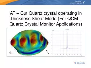
AT – Cut Quartz crystal operating in Thickness Shear Mode (For QCM – Quartz Crystal Monitor Applications)
What is AT – Cut Quartz? • AT – Cut Quartz means Y is the cut direction (thickness direction)and X is the wave propagation direction. • In AT – Cut Quartz, the Y – axis is rotated by 35°21´ • Therefore to obtain correct crystal orientation, one needs to get back to the definition of this crystal cut. • AT – Cut Quartz is represented as yxl 35°21´ • which means “yx” is the initial position of the crystal, where • the first letter “y” is the thickness direction • the second letter “x” is the length direction. • the third letter “l” indicates the axis of rotation (l = length). In this case, “x” is the axis of rotation. • For this configuration, the vibration mode is thickness-shear. Ref: John Buchanan, Handbook of Piezoelectric Crystals for Radio Equipment Designers, 1965.
Geometry Global Coordinate System (Default Setting)
Define a Local Coordinate System Z Y Y X X Rotation about x-axis Z
Visualization of Local Coordinate System Global Coordinate System Local Coordinate System
Subdomain Settings Local coordinate system named “Coordinate system 1” is used to get the correct crystal orientation for AT – Cut Quartz.
Meshing Click on Mesh Selected
Solver Parameters range(4e6,0.3e6,4.9e6) range(4900000,300000/79,5200000) range(5200000,300000,6100000)
Results Plot of total displacement at resonant frequency of 5.093MHz