The MROD
The MROD. Marcello Barisonzi, Henk Boterenbrood, Peter Jansweijer, Gerard Kieft, Jos Vermeulen NIKHEF, Amsterdam Adriaan K önig ,Thei Wijnen NIKHEF and Univ. of Nijmegen, Nijmegen. The Read Out Driver for the ATLAS Muon Precision Chambers. Contents. MROD System Overview

The MROD
E N D
Presentation Transcript
The MROD Marcello Barisonzi, Henk Boterenbrood, Peter Jansweijer, Gerard Kieft, Jos Vermeulen NIKHEF, Amsterdam Adriaan König,Thei Wijnen NIKHEF and Univ. of Nijmegen, Nijmegen The Read Out Driver for the ATLAS Muon Precision Chambers LECC 2002, Colmar
Contents • MROD System Overview • MROD-0 Feasibility Study • MROD-1 Prototype • First Results • Conclusions & Outlook LECC 2002, Colmar
ATLAS MDT Muon Detector ~ 300.000 Drift Tubes ~ 1200 MDT Chambers ~ 200 Towers of 6 Chambers LECC 2002, Colmar
CSM 18 x 24 ch. TDC System Overview Chamber Tower 24 ch. TDC CSM MROD CSM-Link 18 x (GOL)* 24 ch. TDC 6 x 160 MBytes/s S-Link to ROB 24 ch. TDC CSM-Link (GOL) *) http://proj-gol.web.cern.ch/proj-gol LECC 2002, Colmar
1 S 18 CSM Functionality 40 Mbit/s Data/Clock from TDC CSM Serial to Parallel & Clock Domain Separator 1 Gbit/s Separator 18 x 40 Mbit/s Data/Clock from TDC (GOL) Serial to Parallel & Clock Domain Separator 1 Start bit 32 Data bits 1 Parity bit 2 Stop bits 36 bits @ 25 ns = 900 ns 1 Separator word (S) 18 TDC data words 19 words in 900 ns 85 MB/s LECC 2002, Colmar
MROD Functionality Separator word Check (do not store) TDC0, word 1 Build events in a partitioned memory from TDC data fragments (tdc 1) 000…000 Skip (do not store) time TDC2, word 4 TDC3, word 2 Separator word TDC0, word 1 TDC1, word 3 TDC2, word 5 TDC3, word 3 TDC2, word 3 Separator word TDC1, word 2 TDC2, word 2 (tdc 0) 000…000 TDC1, word 1 TDC2, word 1 TDC3, word 1 TDC0, word 0 TDC1, word 0 TDC2, word 0 TDC3, word 0 LECC 2002, Colmar
MROD Form Factor • • 9 U VME board (single slot), 6 CSM Inputs, 1 S-Link Output • • Optionally 2 extra CSM Inputs with “extension” board to • accommodate some special towers with > 6 chambers • CSM Input Interfaces integrated on main board • • 1 MROD Crate (Sub rack) contains: • 12 MRODs (12 Segments) • Up to 4 MROD extension boards • 1 Crate Master with Ethernet Interface (ROD Crate DAQ) • 1 TIM: TTC-Rx Interface Module (incl. ROD Busy) • • @ 192 towers: 192/12 = 16 MROD Crates (1 per Sector) LECC 2002, Colmar
MROD Crate DAQ / DCS ROD Busy Network ROB ROB VME-bus “TIM-bus” ROD CrateDAQ MROD … total ... 12 x MROD TIM (TTCrxInterface) 6 CSMs 6 CSMs From TTC system One MROD Crate services 12 towers (one full sector). In total 16 crates will be required for all MDT chambers. Some MRODs may have 7 or 8 input links via “slave” MROD input cards. LECC 2002, Colmar
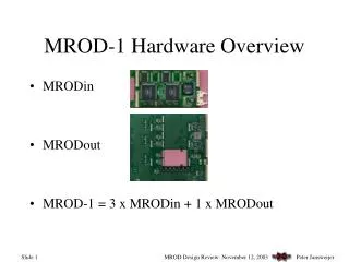
CSM-Link CSM-Link CSM-Link CSM-Link CSM-Link CSM-Link MROD Throughput MROD MROD-in MROD-out MROD-in S-Link MROD-in Average 5 hits per TDC + header + trailer = 7 words/event Per tower of 6 chambers max. 88 TDCs * 7 600 words/event (= 2.4 kB/event) Worst case est.: @ 100 kHz L1A rate 240 MB/s per MROD Calculation based on actual tower layout (J.Chapman): max. rate < 60 MB/s per MROD LECC 2002, Colmar
MROD-0 Feasibility Study CSM MROD MROD-in CSM MROD-in MROD-out CSM MROD-in ROB CSM MROD-in CSM MROD-in MROD-in CSM LECC 2002, Colmar
(SHARC-I) LECC 2002, Colmar
MROD-0 Prototype sorted TDC-data over SHARC Link MROD-in MROD-out MCRUSH SHASLINK LECC 2002, Colmar
MROD-0 Input Channel MCRUSH 1 MB ZBT Memory Input FIFO Output Tetris Register FIFO Control SHARC 6 Sharc links @ 40 MB/s each Data FIFO Length FIFO FPGA Control/Status Error signaling LECC 2002, Colmar
MROD-0 Output Channel SHaSLINK PCI bus SHARC PCI 9054 6 SHARC Links @ 40 MB/s each Altera 10K10A S-Link max. @ 160 MB/s LECC 2002, Colmar
MROD-0 Emulation Hardware MROD-0 sorted + merged TDC-data sorted TDC-data TDC-data MCRUSH SHASLINK ROBSIM CRUSH + SHASLINK MROD-in (3x) MROD-out CSMSIM SHASLINK 2 0 3 1 0 0 1 3 fragment lengths xxxxx Module type S-Link optionally double/triple MROD-in output thus simulating 2 or 3 MROD-ins SHARC-links event fragment lengths via SHARC-link simulates future MROD-1 functionality LECC 2002, Colmar
MROD CSMSIM MRODIN MRODOUT ROBSIM LECC 2002, Colmar
MROD-0 Performance Study Results MROD CSMSIM MRODIN MRODOUT ROBSIM LECC 2002, Colmar
MROD-0 Performance Study Results MROD CSMSIM MRODIN MRODOUT ROBSIM LECC 2002, Colmar
MROD-0 Performance Study Results MROD CSMSIM MRODIN MRODOUT ROBSIM LECC 2002, Colmar
MROD-0 Performance Study Results MROD CSMSIM MRODIN MRODOUT ROBSIM LECC 2002, Colmar
MROD-0 Performance Analysis • Measured event rate for single output SHARC-I @ 40 MHz with 2 and 3 emulated CSM inputs: maximumevent rates of 70 and 50 kHz respectively are measured. • MROD-1 will use the SHARC-II @ 80 MHz: both the processing speed and the bandwidth increase proportionately event rate 100 kHz ? • use 2 SHARC-II processors for MROD-out. LECC 2002, Colmar
Memory FPGA MROD-1Prototype SHARC VME64x FPGA Memory SHARC (2x) SharcLinks 3x (intotal) Memory FPGA TTC Interface SHARC FPGA Memory LECC 2002, Colmar
SHARC-II LECC 2002, Colmar
The ADSP-21060 and the ADSP-21160 SHARCs • • 40 MHz / 80 100 MHz CPU (SIMD mode) • 512 KB/512 KBinternal memory • 6 x40/ 80 100MB/s links. Throughput of all links simultaneously • is 160 / 480 600 (?) MB/s, without disturbing the CPU. • No handshaking on links, but hardware XON-XOFF protocol, • 10 / 14DMA channels • Support for bus arbitration: at max. 6 SHARCs can be connected to a common • bus without glue logic. Each SHARC can access the internal memories of each other • SHARC. The SHARCs also provide support for a so-called host interface, which can • act as an additional master on the common bus. • Fast interrupt servicing due to the presence of shadow registers • Two 40 Mbit/s / 40 50 Mbit/s (at max.) synchronous serial ports • Can be booted via link 4 LECC 2002, Colmar
MROD-1 Form Factor • • 9 U VME boards, 2 units wide • 1 S-Link output on daughter board • 6 GOL inputs on daughter boards • • SHARC II (ADSP21160) DSPs: • (3 for input, 2 for output processing) • Altera APEX FPGAs, 200k gates • TIM bus over special P3 back plane • VME64x interface GOL daughter boards Input Input S-Link daughter board Input Output Motherboard LECC 2002, Colmar
MROD-out Board LECC 2002, Colmar
MROD-in Board LECC 2002, Colmar
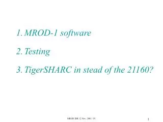
MROD-1 Prototype Status • Fully functional MROD-1 modules exist: • 7 MROD-in and 3 MROD-out boards have all been extensively tested, also in conjunction with simulated data via the input link. • Software to boot the SHARCs via the VME bus and a run-time environment providing file and terminal I/O via a server program under both the LynxOS and Linux operating systems on the VME processor is available. LECC 2002, Colmar
MROD-1 Prototype Status (Contd.) • Current MROD-1 SHARC software is largely ported from the MROD-0 prototype. Further development of this code is required. • This process is hampered by a compiler which is not fully reliable, in particular when it comes to optimization which in turn is very important to obtain good performance. • Transition to SHARC-II DSPs has not always been completely straightforward: work-arounds have been implemented. See example below …. LECC 2002, Colmar
MROD power-up modification LECC 2002, Colmar
First MROD-1 Results • Preliminary single channel tests with a CSM simulator show a sustainable 125 kHz event rate with 18 simulated TDCs with five 32-bit words per event. • Equivalent of 45 MBytes/sec. • Rate of 125 kHz appears to be limited by the input (i.e. the CSM simulator) rather than by the MROD-1 itself. This is being investigated. LECC 2002, Colmar
Conclusions & Outlook • The first MROD-1 test results are in line with the MROD-0 results and the SHARC-I to SHARC-II extrapolation. • Results are encouraging. Improvements still possible. More tests need and will be done. • Development of a GOL receiver card to connect to the CSM is well underway. • System integration tests with both the CSM and the DAQ-1 and ROD CRATE DAQ follow soon. • Application in NIKHEF local Cosmic Ray Test Stand. LECC 2002, Colmar