Upgrading the Level-1 Endcap Muon Trigger Processor for Enhanced SLHC Operations in CMS
This paper discusses the design considerations for upgrading the Level-1 Endcap Muon Trigger Processor of the CMS experiment in preparation for SLHC operations. The current system consists of 12 Sector Processors (SPs) that identify muon tracks, with a focus on optimizing performance amidst increased luminosity. Proposed solutions include enhancements to filtering capabilities and bandwidth increases, as well as improved algorithms for track assembly and ghost cancellation. This upgrade aims to ensure reliable and efficient muon detection for future experiments.

Upgrading the Level-1 Endcap Muon Trigger Processor for Enhanced SLHC Operations in CMS
E N D
Presentation Transcript
TWEPP09 Design Considerations for an Upgraded Track-Finding Processor in the Level-1 Endcap Muon Trigger of CMS for SLHC operations D. Acosta, M. Fisher, I. Furic, J. Gartner, G.P. Di Giovanni, A. Hammar, K. Kotov, A. Madorsky, D. Wang University of Florida/Physics, POB 118440, Gainesville, FL, USA, 32611 L. Uvarov Petersburg Nuclear Physics Institute, Gatchina, Russia M. Matveev, P. Padley Rice University, MS 61, 6100 Main Street, Houston, TX, USA, 77005
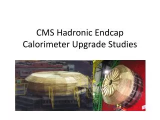
CMS Endcap Muon System φ θ, η TWEPP09
CMS Endcap Muon System TWEPP09
CMS Endcap Muon Trigger • Each of two Endcaps is split into 6 sectors, 60° each • Each sector is served by one Sector Processor (SP) • Total 12 SPs in the entire system • CMS trigger requires us to identify distinct muons • Each SP can build up to 3 muon tracks per BX Trigger sector 60˚ TWEPP09
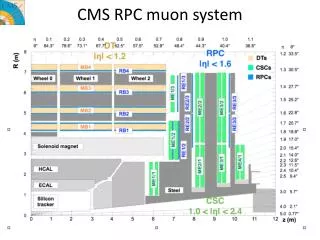
Cathode Strip Chamber • CMS Endcap uses Cathode Strip Chambers (CSC) • 6 layers • Strips in φdirection • Wires in θ direction TWEPP09
Present CSC Muon Trigger structure • Trigger information • Wiregroup patterns (detected by on-chamber ALCT board) • Strip hits Trigger primitives 2 per chamber 18 per station 90 total Muon Endcap Trigger sector (60°) Stations ME4 ME3 ME2 • Trigger Motherboards • (UCLA) • One per chamber • Strip pattern detection • Trigger primitive building background Port Cards (Rice) One per station 1/6 filtering Track Fibers (~100 m) Station ME1b 3 (best) primitives per station 15 total Station ME1a • Sector Processor (UF) • Complete 3-D tracks assembled from primitives • Up to 3 tracks per BX TWEPP09
Problems and solutions • Current design is totally adequate for LHC luminosity • 2 LCTs (di-muon signal) + 1 (background) = 3 LCTs per Port Card per BX • With luminosity upgrade, we expect ~7 LCTs per Port Card per BX. • Preliminary simulated data, no measurements so far • Reality could be worse • Port Card becomes a bottleneck • Solution: • Keep 2 Trigger Primitives per chamber • Bring all LCTs to SP (18 per Port Card per BX), no filtering • May keep the filtering option in Port Cards, in case it’s needed • See this talk by Darin Acosta for explanation of above numbers • Based on simulations performed by A. Safonov and V. Khotilovich (TAMU) TWEPP09
CSC Trigger upgrade • Trigger information • Wiregroup patterns (detected by on-chamber ALCT board) • Strip hits Trigger primitives 2 per chamber 18 per station 90 total Muon Endcap Trigger sector (60°) • Trigger Motherboards • (UCLA) • One per chamber • Strip pattern detection • Trigger primitive building Upgraded Port Cards (Rice) One per station 1/6 filtering Fibers (~100 m) 18 primitives per station 90 total • Upgraded • Sector Processor (UF) • Complete 3-D tracks assembled from primitives • Up to 3 tracks per BX TWEPP09
Port Card upgrade • Cost: • Port Card replacement system-wide (60 pcs) • Faster serial links PortCard SP • Currently used: 1.6 Gbps • Available now: 10+ Gbps • Link speed increase by a factor of 6.25 or more • 10+Gbps links will be run asynchronously to reach full speed • Required bandwidth increase (in terms of trig. primitives): 18 / 3 = 6 • Looks like we don’t need additional fibers • However, may need to replace them all • Another option: parallel multichannel serial links TWEPP09
SP upgrade SP logic structure Conversion of trigger primitives to coordinates BX adjustment to 2nd trig. primitive Pt, φ, η calculation Multiple Bunch Crossing Analysis Main upgrade targets Extrapolation units Track assembly Sorting, ghost cancellation TWEPP09
Trig. Primitives Coordinates • Currently performed in large 2-stage LUTs • Unacceptable for upgrade – too much memory • 4MB per trig. primitive • 6 times more trig. primitives in upgraded design • Need ~400 MB per SP Wiregroup pattern φ Strip pattern LUT η Chamber ID TWEPP09
Trig. Primitives Coordinates • For upgrade: • Make conversion inside FPGA • Combine LUTs and logic to reduce memory size • We receive Trig. Primitives from all chambers • no need to analyze Chamber ID • saves precious LUT input bits • Use different angular coordinates – φ with half-strip resolution and θ • Why θ ? • Allows for uniform angular extrapolation windows, no need to adjust them depending on θ • Why φ with half-strip resolution? • Makes conversion easier, for 80-strip 10° chambers (ME1/2, ME2/2, ME3/2, ME4/2) as easy as one addition with fixed value. • Easier to handle in FPGA TWEPP09
Wiregroup θ θ1 8-bit Wiregroup 5 to 7-bit θ 8-bit Wiregroup 6-bit + LUT 32 to 128 cells LUT θ2 8-bit + Strip1 6-bit θ conversion all chambers except ME1/1 θ corrections 4-bit LUT WG MSB 2-bit Strip2 6-bit WG1 θ1 WG1 θ2 LUT WG MSB 2-bit WG2 θ1 WG2 θ2 ME1/1 θ conversion θ corrected and duplicated because of wire tilt (if chamber has 2 trig. primitives) TWEPP09
Strip φ Half-Strip 7 or 8-bit φ in sector 10-bit ×F + Initial φ 10-bit (fixed) corrected φ in sector 12-bit CLCT pattern 4-bit φ correction 2-bit LUT Use built-in multiplier or LUT. “F” factor depends on chamber type TWEPP09
Geometry constraints for track building • Consider only physically allowed chamber combinations from one disk to the next in track extrapolations and in track assembly to reduce logic resources • Not all combinations need testing due to • Limited bending in magnetic field (<10°) in φ • Chamber coverage structure in θ view η(θ) TWEPP09
Geometry constraints for track building ME1ME2 Total: 52paths ME1ME3 Total: 58 paths - means path to chamber directly behind TWEPP09
Geometry constraints for track building ME1ME4 Total: 42paths ME2ME3, ME2ME4, ME3ME4 Total: 33 paths - means path to chamber directly behind TWEPP09
Extrapolation units • What does extrapolation unit do? • Compares trigger primitives from 2 stations (chamber layers) • Checks that they are within certain “window” relative to each other • |φA – φB| < max Δφ • |θA – θB| < max Δθ Window Trig. primitive from Station A Trig. primitive from Station B TWEPP09
Number of extrapolations more θ EUs because of ME1/1 θ duplication • 2002 SP design has 63 extrapolations (φandη) • Upgraded design is ~18 times larger • Current FPGAs are 3 times larger than in 2002 • Need additional factor of ~6 increase by SLHC Phase 1 upgrade – or several FPGAs • Try all wire-strip combinations for each CSC, to account for “ghosts” • Currently done only for station 1 TWEPP09
Track Assembly Units • What does Track Assembly Unit do? • Analyzes extrapolation results • Attempts to build the best track from available trigger primitives TWEPP09
Track Assembly Units • Implementation: • Find best extrapolations • minimum φ difference between primitives • valid θ extrapolations • Make track out of corresponding segments • Need to do that for each trig. primitive in key stations Number of trigger primitives received from key stations TWEPP09
Sorting and Ghost Cancellation • Purpose: • Select 3 best tracks out of all track candidates • Remove “ghosts” – multiple track candidates created by the same physical track • Implementation: • Compare each candidate with all others • Problem: • Sorting and Ghost Cancellation is already the largest part of SP design • Logic size grows as square of the number of track candidates • Need ~30 times more logic than current design • May not be able to afford this even with FPGAs available at the time of upgrade! TWEPP09
Halo track detection • Same as collision tracks, except: • Convert Wiregroup to Radius • Perform Radius extrapolations instead of θ • Different Geometry constraints • Fewer Extrapolation paths TWEPP09
Pattern-based detection • Investigating another approach: • Pattern-based detection • Separately in φ and θ • Once the patterns are detected, merge them into complete 3-D tracks • Benefits: • Logic size reduction • Certain processing steps become “natural”, logic for them is greatly simplified or removed • Multiple Bunch Crossing Analysis • Ghost Cancellation ME 1234 Station 32 16 8 4 2 1 1 1 2 4 8 16 32 Number of Strips ORed One of the patterns Possible φ pattern envelope structure TWEPP09
CSC + Tracker = Better Trigger • Investigating challenges of matching CSC triggers with Tracker • Should be able to reach better rate reduction by: • Using Tracker to confirm CSC trigger candidates • Track fit improvement TWEPP09
Conclusions • Importing all trigger primitives from all chambers: • Promising but not certain • May need to return to filtering in Port Cards • Need at least 7 trig. primitives per sector • Under investigation: • Pattern detection approach • CSC Tracker matching TWEPP09