Download
1 / 12
120 likes | 241 Views
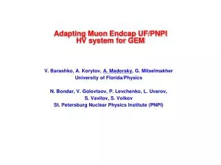
Adapting Muon Endcap UF/PNPI HV system for GEM. V. Barashko , A. Korytov , A. Madorsky , G. Mitselmakher University of Florida/Physics N. Bondar , V. Golovtsov , P. Levchenko , L. Uvarov , S. Vavilov , S. Volkov St. Petersburg Nuclear Physics Institute (PNPI).

E N D
Adapting MuonEndcap UF/PNPIHV system for GEM V. Barashko, A. Korytov, A. Madorsky, G. Mitselmakher University of Florida/Physics N. Bondar, V. Golovtsov, P. Levchenko, L. Uvarov, S. Vavilov, S. Volkov St. Petersburg Nuclear Physics Institute (PNPI)
UF/PNPI HV system architecture All MuonEndcap chambersexcept ME1/1 9006 channels (w/o spares) 11000+ after ME4/2 upgrade Multiwire HV cables, 100 m, one per 18 distribution boards • Primary HV power supplies: off the shelf • Master board: One output per distribution board. Regulates voltage 0-4KV (VMAX), measures current on each output. • Remote Distribution board: powers one large or two small chambers (36 outputs max). Regulates voltage 1KV down from VMAX, measures current on each output. Each output can be disconnected from HV if necessary.
Primary HV Power supply • Off the shelf unit • Matsusada AU type • Up to 5KV output • 60 mA • Control : RS-232 • Overcurrent protection • Door switch • Floating output
Master board • 8 channels • Full range regulators 0-4KV • Up to 1.5 mA per channel • NOT rad-hard • Located in S1 (control room) • Voltage and current measurementon each channel
Distribution board • Up to 38 channels • Partial range regulators (~1KV down from input V) • Each channel can be disconnected from load • Remote-blow fuse • Up to 100 uA per channel • Rad-hard, magnetic field-tolerant • Located in UXC (CMS cavern), near disks • On each channel: • Voltage and current limit programmable • Voltage and current measurement • Voltage resolution: • ~1V • Current measurement resolution: • 100 nA
Software Calibration utility Trip profile analyzer Expert GUI (Java) Shows V and I on each segmentin each chamber Lets you control all parametersindependently of DCS
Safety • Purposes • Safety of the personnel • Protection of the end-loads • Protection of system components • Fail-safe devices: • Interlocks • All long cables • Primary HV PS overvoltage protection • Remove PHVPS AC power in case of overvoltage • Hardware watchdog • Monitors main control software loop activity • Turns PHVPS off if activity is missing for ~10 sec • Protects against: • software bugs • computer hardware failure • computer power cut-off • Overvoltage and overcurrent protection on each output channel • All thresholds programmable • Dead or disconnected board detection
What can we do for GEM • Each voltage input should be powered from its own regulator • Voltages are individually adjustable • Currents are measured on each channel • GEM segment ganging will be needed • Table shows one possible option • CMS Distribution board can have up to 38 outputs • Two GEM chambers, 19 outputs each • Other ganging options possible
Required R&D • Polarity reversal • CMS CSC HV boards are designed for positive output • Provisions for polarity reversal made • This has not been tested • Regulators need significant rework • Multiple output voltages • Distribution boards (DB) have a single HV input. • All output voltages are regulated down from input voltage. • Maximum regulating range is ~1KV • Need multiple inputs on DB
Another option • Low-current active divider • Voltages are fixed - no adjustment • All foils on the same layer ganged together • Not based on current DB • New development required
Conclusions • Two options are proposed • Currently under discussion with PNPI colleagues • Will have a meeting with A. Marinov, PNPI colleagues and me this week, for detailed discussion