Embedded Systems Memory Expansion Lecture
Explore various memory types, expansion methods, interfacing techniques, and issues in embedded systems. Learn about memory characteristics such as volatility, persistence, speed, reprogrammability, and explore ROM, EEPROM, RAM, and SRAM examples. Discover how to address memory issues like bus loading and the memory wall, and explore solutions like code shadowing, caching, wider bus access, and branch target caching in this comprehensive lecture.

Embedded Systems Memory Expansion Lecture
E N D
Presentation Transcript
Memory Expansion Lecture 20 Embedded Systems
In These Notes . . . • Memory Types • Memory Expansion • Interfacing • Parallel • Serial • Direct Memory Access controllers Embedded Systems
Memory Characteristics and Issues • Volatility - Does it remember when the power fails? • Persistence - How long does it remember when there is power? • Speed – How quickly can it be read or written? • Reprogrammability • Speed is often an issue for nonvolatile memories • Maximum number of W/E cycles • Programming voltage • Cost • Temperature Sensitivity - EPROMs forget at high temperatures Embedded Systems
Types of Memory - ROM • Mask • A custom ROM mask pattern is created • Large minimum order, NRE costs • PROM • Program by burning fuses. Apply a high voltage for a certain amount of time. • Not erasable • UV EPROM • Program by squeezing charge into floating transistor gate with high voltage • Erase entire memory at once with UV radiation Embedded Systems
Types of Memory - EEPROM • EEPROM • Can erase a byte at a time electrically • Limited reprogrammability: e.g. 100,000 cycles • Slow programming (up to 10 ms per byte) • Flash EEPROM • Can erase entire chip, or just certain blocks • May have limited reprogrammability: e.g. 1,000 cycles for some low-end units • May have slow programming • Serial or parallel interface Embedded Systems
Types of Memory - RAM • SRAM • Use two or six transistors per bit • Fast - 10 ns or less • DRAM • Use one transistor per bit • Acts like a capacitor, discharges in a few milliseconds • Incredibly cheap, but need to refresh each bit periodically • Slower than SRAM - 60 ns • Tricks to speed up access (e.g. page mode) Embedded Systems
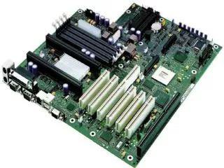
Parallel Memory Interface • 1920 bytes are not enough for our data logger! • We want to store up to 32 kBytes of data • Choose a microcontroller with more memory? • Not available, or too expensive • Instead choose a microcontroller with a memory expansion mode • M16C/62 Modes for M16C/62 MCU Embedded Systems
SRAM Example – IDT71256L • 32k x 8 SRAM Embedded Systems
IDT71256L Read Timing Embedded Systems
IDT71256L Write Timing Embedded Systems
External Memory Access – Separate Buses • Chip Select • Partial vs. Full Decoding • Power Consumption MCU SRAM D7-D0 I/O7-I/O0 A14-A0 A14-A0 A15 ~CS ~WR ~WE ~RD ~OE Write Read Data from SRAM Data from MCU D7-D0 A15-A0 Adx from MCU Adx from MCU ~WR ~RD Embedded Systems
External Memory Access – Multiplexed Buses • Use a latch to hold the low byte of the address • Saves pins SRAM I/O7-I/O0 MCU AD7-AD0 A7-A0 ALE A14-A8 A14-A8 A15 ~CS ~WR ~WE ~RD ~OE Write Read AD7-AD0 Low Adx SRAM D Low Adx MCU D A15-A8 Hi Adx from MCU Hi Adx from MCU Latch Out Low Adx from MCU Low Adx from MCU ALE ~WR ~RD Embedded Systems
Multiple External Memories • Decoder selects a single memory chip • Output 0 active when A16:A15 = 00. Address = 0 0xxx xxxx xxxx xxxx = 00000h to 07FFFh • Output 1 active when A16:A15 = 01. Address = 0 1xxx xxxx xxxx xxxx = 08000h to 0FFFFh • Output 2 active when A16:A15 = 10. Address = 1 0xxx xxxx xxxx xxxx = 10000h to 17FFFh MCU SRAM 1 SRAM 2 ROM 1 D7-D0 I/O7-I/O0 I/O7-I/O0 I/O7-I/O0 A14-A0 A14-A0 A14-A0 A14-A0 A16-A15 ~CS ~CS ~CS ~WR ~WE ~WE ~RD ~OE ~OE ~OE 1 2 0 Decoder Embedded Systems
Issue – Bus Loading • Microcontroller has a limited output drive capacity on the data and address buses • e.g. 100 pF for an AMD MCU • Each device on the bus adds capacitance • 11 pF for each input on IDT SRAM chip • This leads to increased time delay until bus reaches valid voltage • M16C lowers threshold voltages when accessing external memory • Solution: add buffers Embedded Systems
Issue - The Memory Wall • Difference in read cycle times for memories • Internal memories • SRAM: blazingly fast • Flash: down to 40 ns • External parallel-interface memories • SRAM: down to 10 ns • Flash: down to 55 ns • Memory Wall: flash memory can’t keep up with fast processors • External flash: 1/55 ns = 18 MHz • Internal flash: 1/40 ns = 25 MHz • Need a mechanism to speed up access to data stored in flash memory Embedded Systems
Solutions to the Embedded Memory Wall • Code shadowing • Use flash memory to hold the program • At boot-time load the program into faster SRAM • Execute the program out of SRAM • Problem: extra memory costs money • Cache • Use a small fast SRAM with a cache controller to hold commonly used data • Problem: unpredictable access times make it hard to guarantee predictable timing (e.g. real-time is difficult) • Wider bus to memory • Access multiple (e.g. four bytes) at a time. • Fetching byte N also prefetches bytes N+1, N+2 and N+3 • Works well for sequential accesses • Problem: Still incurs a delay for random accesses (e.g. branch) • Branch target cache • Cache multiple bytes from targets of branch instructions • Problem: Unpredictable access times. But may be able to lock cache. • Could also cache the beginning of all ISRs Embedded Systems
Storing Large Amounts of Data • What if we want to store more data than fits into our processor’s address space? A. Use a memory paging scheme • Use a register (or output port) to hold the upper bits of the address • This register selects which page of memory we will access • Control the register with a page select function • This doesn’t fit in well with C, as the compiler doesn’t know about your custom paging scheme • Some MCUs support paging, and the compilers can compile for it B. Use a serially-interfaced memory (inexpensive) • Communicate with the memory over a few data lines • C compiler doesn’t know about this memory either • May want to introduce some kind of file system to manage information in the expanded memory Embedded Systems
RDY/BSY Serial Interface Flash RDY/BSY output provides the device status NOR Flash Memory Array with Small Pages RESET input allows the System to Terminate Any Operation FLASH MEMORY ARRAY Write Protect Provides method to protect a portion of the memory Array RESET Multiple Data Paths for Reading and Writing PAGE SIZE = BUFFER SIZE WP BUFFER 2 BUFFER 1 SCK CS High Speed Clock I/O INTERFACE Chip Select Input allows multiple devices on the same bus SI SO Dual SRAM Buffers to provide enhanced flexibility and simultaneous read or write operations DataFlashTM (Atmel) SPI compatible Serial Interface Embedded Systems
Details for DataFlash • Numbers • 1 Mbit – 128 Mbit capacities available • Page sizes from 264 to 1056 bytes • up to 20 MHz SPI interface speed • Page->Buffer transfer/compare: < 250 us • Page erase: < 8 ms • Page program: < 14 ms • C source code for interface available • Flash file system (FAT12 and FAT16) • Compression/decompression • Error detection and correction • Wear leveling • Automatic page rewrite • Commands (hardware) • Page read • Transfer page to buffer • Compare page with buffer • Buffer read, write • Program page from buffer (with or without erasing) • Program page through buffer • Page erase • Block erase (8 pages) • Automatic page rewrite Embedded Systems
Moving Data Efficiently • Sometimes we just need to move data… • Loading a packet from an Ethernet interface • Loading a video frame buffer • Initializing an array to zero • Loading an audio output buffer with audio samples • Very slow when performed in software Loop: mov.w _source[A0], _dest[A1] add.w #2, A0 ; increment src. ptr add.w #2, A1 ; increment dest. ptr cmp.w A0, R0 ; assume R0 is end ptr jle Loop • Consider a UART ISR which takes 50 cycles • Actually just need to move a byte from the UART to a buffer • 50 cycles/16 MHz = 3.125 us • Limits us to maximum 320 kHz bit rate (100% CPU utilization) Embedded Systems
Direct Memory Access • Sequence of activities • Controller takes bus from CPU • Performs data transfer • Can interrupt CPU to signal completion • Control Registers • Start and destination addresses • Transfer length • Status • DMA Controller preempts CPU, may need to interleave accesses to ensure progress for CPU • UART DMA: 2 cycles • At 320 kBps, CPU utilization = 320 kHz * 2/16 MHz * 100% = 4% utilization Embedded Systems
M16C/62 DMA Controllers • 2 DMACs, 0 and 1 • Control Registers • Source Address SAR0, SAR1 • Destination Address DAR0, DAR1 • Transfer Count TCR0, TCR1 • DMA Request Cause • INT1, Timer, software trigger, UART Tx, UART Rx, A/D conversion complete • Transfer mode • Enable • Byte or word transfer • Single or repeat transfer • Source address increment or fixed • Destination address increment or fixed Embedded Systems