Download
1 / 15
150 likes | 272 Views
This document explores the intricate design of a carrier bus and readout chip for advanced pixel detectors. It presents cross-sectional layouts, bonding connections, and the integration of power supplies and resistors in a compact dimension. The design incorporates various components such as analogue and digital power supplies, cooling systems, and signal planes, all crucial for efficient detector operation. The study discusses multiple solutions and prototypes developed at CERN, highlighting material specifications and bonding procedures for optimal performance in high-energy physics applications.

E N D
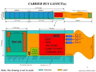
CARRIER BUS LAYOUT(a) ± 193 mm ladder2 ladder1 Power supplies connector Pilot & link drivers Flexible Extender 13.92mm 16.8 mm 70.72 mm 70.72 mm 1000mm 13.62 mm 50 mm Pixel chip 32 x 425µ Data MCM - pilot - GOL - Serializer - Laser drivers - Analogue part Controls Clk 256 x 50µ 15.86 mm 12mm Pull up network resistors Decoupling capacitors Bonding wires Note: the drawing is not to scale Aluminium copper Michel Morel EP/ED 09/2000
CARRIER BUS + DETECTOR AND READOUT CHIP CROSS SECTION (solution A) 15.86mm 1mm 13.92mm PIXEL DETECTOR BONDIND WIRES 600µ READOUT CHIP 6 5 Via between horizontal and vertical lines 4 200µ 3 2 1 CARBON FIBER SUPPORT 6 ANALOG_GND 25µ 5 ANALOG_POWER 25µ 4 VERTICAL LINES 5µ 3 HORIZONTAL LINES 10µ 2 DIGITAL_POWER 25µ 1 DIGITAL_GND 25µ Aluminium COOLING TUBE Polyimide Note: the drawing is not to scale Michel Morel EP/ED 05/00 Michel Morel EP/E
PIXEL BUS + DETECTOR AND READOUT CHIP CROSS SECTION (solution B) 2mm 11.92mm 6 6 5 5 4 PIXEL_BUS 0.2 3 Aluminium 2 2 Polyimide 1 1 PIXEL DETECTOR Glue 0.6 READOUT CHIP 1 ANALOG_GND 25µ 2 ANALOG_ POWER 25µ 3 HORIZONTAL LINES 10µ 4 VERTICAL LINES 5µ 5 DIGITAL_POWER 25µ 6 DIGITAL_GND 25µ ? COOLING TUBE CARBON FIBER SUPPORT Michel Morel EP/ED 09/2000
CARRIER BUS + EXTENDER & MCM CROSS SECTION 12mm Opt. Link Opt. Link Opt. Link Pilot & GOL MCM 1.15mm MCM Carrier 400µ extender 250µ Carrier bus 200µ Glue Aluminium Polyimide Copper Note: the drawing is not to scale Michel Morel EP/ED 09/2000
CARRIER BUS CROSS SECTION (solution A) 6) Analogue ground 5) Analogue power 4) vertical lines 3) Horizontal lines 200µ 2) Digital power supply 1) Digital ground Glue 5µ Polyimide 15µ Aluminium 25µ Aluminium 10µ Aluminium 5µ Liquid Polyimide 5µ Michel Morel EP/ED 09/00 Michel Morel EP/ED 0
EXTENDER CROSS SECTION 12mm 250µ 2 3 4 1 5 5 6 6 2mm TOP VIEW 1m 12mm Bonding sector( NI.AU ) Power supplies connector 6 - Bias Detector (1mA) 5 - MCM power (1A) Copper 150µ 4 - Digital Power (3A) 3 - Digital GND 2 - Analogue Power (3A) Kapton 1 - Analogue GND Note: the drawing is not to scale Michel Morel EP/ED 09/00
EXAMPLES OF BONDING CONNECTIONS (solution A) Pixel_chip Bonding wire 400µ Analogue ground Analogue power Vertical lines Michel Morel EP/ED 09/00
EXAMPLES OF BONDING CONNECTIONS (solution B) 400µ Pixel detector Digital ground digital power Vertical lines Analogue power Analogue ground Pixel readout chip Michel Morel EP/ED 09/00
CARRIER BUS PROTOTYPE MADE AT CERN Aluminium: 15µ Kapton: 50µ Glue: 10µ Total thickness:300µ 200mm x 17mm 4 aluminium layers bus = 81 lines 100µ Michel Morel EP/ED 09/00
EXAMPLE OF BONDING CONNECTIONS BETWEEN THE PIXEL CARRIER AND HIS SUPPORT INTERFACE (power supplies connections)
These layers have been cut mechanically Signals layer polyimide VDD plane
Digital ground plane (GND) Digital power plane (VDD) Vertical Signal plane Analogue power plane (VDDA) Analogue ground plane (AGND) These layers have been cut chemically Digital power plane (VDD) Vertical Signal plane Analogue power plane (VDDA) Analogue ground plane (AGND)
TOP VIEW OF ALICE PIXEL DETECTOR ONE SECTOR REPRESENTED (SOLUTION A) Pixel_chip Extender carrier bus ladder Pilot & Optical link Image:INFN(Padova) Michel Morel EP/ED 09/00
ALICE PIXEL DETECTOR Image:INFN(Padova)