Download
1 / 40
400 likes | 576 Views
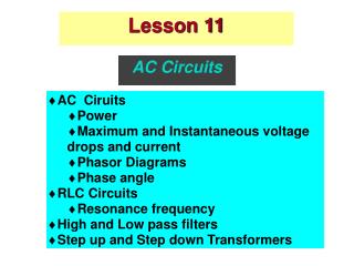
Lesson 11. Lesson 11. AC Circuits. AC Ciruits Power Maximum and Instantaneous voltage drops and current Phasor Diagrams Phase angle RLC Circuits Resonance frequency High and Low pass filters Step up and Step down Transformers. AC Generator. AC Generator. AC emf source.

E N D
Lesson 11 Lesson 11 AC Circuits • AC Ciruits • Power • Maximum and Instantaneous voltage drops and current • Phasor Diagrams • Phase angle • RLC Circuits • Resonance frequency • High and Low pass filters • Step up and Step down Transformers
AC Generator AC Generator
rms current Effective ( Integrated ) values of I and V ( ) ( ) = i t I sin t w max p 2 w = p = 2 f ; T is the period of oscillation T ( ) ( ) = Instantaneous power i t v t ( ) ( ) 2 = = 2 2 w Heat dissipated = Power used in load i t R I R sin t m Average power over one cycle ò ò T T 2 1 1 I R ( ) ( ) = 2 2 w = 2 2 w = m P I R sin t dt I R sin t dt ave m m T T 2 0 0 Define I = 2 Þ = m P I R I ave rms rms 2
ac-R circuit Veff and v(t) Ieff and i(t) t)
Phasor diagram for R Phasor Diagram iR(t) IRmsin(t)= iR(t) t Current through Load Resistance
Phasor diagram for R cont. Phasor Diagram vR(t) vR(t) VRmsin(t)= t PD across Load Resistance
ac-C circuit vC(t) iC(t) t) iC(t) vC(t) Current in Circuit and PD across Capacitor t
ac-L circuit vL(t) iL(t) t) vL(t) t Current in Circuit and PD across Inductor iL(t)
Summary The phase angle between the current and the voltage: In the resistor is 0 rad In the capacitor is - rad ( Current Ahead) In the inductor is +rad (Current Behind)
series ac-RLC circuit Series RLC circuit
Instantaneous current Current through all elements is the same Thus the instantaneous PD’s must be out of phase
Picture Total Potential Drop across R, L & C.
Phasor Diagram for RLC circuit I vL(t) vR(t) vC(t)
Instantaneous PD Why
Phasor Diagram for RLC circuit II vL(t) vRLC(t) vR(t) vC(t)
Instantaneous PD as projection onto y-axis vRLC(t) v(t2) v(t1)
Phase Angle vRLC(t) - V V ( ) f = Lm Cm tan V Rm - - I X I X X X = = m L m C L C I R R m Phase Angle æ ö - X X - 1 f = L C ç ÷ tan è ø R
Impedance The magnitude of the Total Potential Phasor is ( ) 2 = 2 + - V V V V m R Lm Cm ( ) ( ) 2 2 = 2 2 + - = 2 + - I R I X I X I R X X m m L m C m L C = I Z m ( ) 2 = 2 + - Impedance : Z R X X L C
Generalized Ohm's Law. ( ) 2 = 2 + - Impedance Z R X X L C
Power Factor Power is only used in AC circuit in load resistance ( ) ( ) 2 = P t i t R (energy is not used in inductor or capacitor) ( ) = 2 2 w f t I sin - R m (current is always in phase with PD across total resistance) 2 I 2 = P = I R R m ave rms 2 ß e æ ö R e e ç ÷ ( ) = = f rms I R I I cos ç ÷ rms rms rms rms rms Z Z è ø ( ) f = cos Power Factor
Angular frequency dependence Power and current depend on angular frequency of circuit
e Max I ; Min Z V ( ) w = = m m I ( ) ( ) w w m Z Z ( ) ( ) 2 w = + - 2 Z R X X L C æ ö 2 æ ö w - 2 2 1 LC 1 = 2 + w - = 2 + ç ÷ ç ÷ R L R è ø w w è ø C C ( ) w w - = 2 Z is a minimum when LC 1 0 which occurs when 1 w = w = 0 LC Û = X X L C
Power as a function of 2 V R 1 1 ( ) ( ) w = w = 2 m P I R ( ) ave m 2 w 2 2 Z 2 2 1 V R 1 V R = = m m æ ö 2 2 L 2 1 2 ( ) 2 + w - + w - w 2 2 2 2 ç ÷ R L R è ø w 2 0 w C w 2 2 1 V R = m ( ) 2 2 2 w 2 + 2 w 2 - w 2 R L 0
Resonance Circuit uses most power / current when it is in RESONANCE with applied frequency
Imax and Pave versus Pave Im
Quality of circuit • Width of Power curve is a measure of the QUALITY of the circuit • Small width - High Quality • Sharpness of response to external frequency
RC Filters I RC Filters Low Pass Filter Vout Vin
RC Filters II RC Filters High Pass Filter Vout Vin
Transformers I Step up and Step down Transformers
Transformers II F d = - B V N 1 1 dt F d = - B V N 2 2 dt Fluxes are the same N = V 2 V 2 1 N 1