Download
1 / 22
230 likes | 550 Views
Aeroacoustics and Aerodynamic Performance of a Rotor with Flatback Airfoils. 2010 European Wind Energy Conference Warsaw, Poland 23 April 2010. Matthew Barone, Josh Paquette Sandia National Laboratories, Albuquerque, NM Eric Simley University of Colorado, Boulder, CO Monica Christiansen

E N D
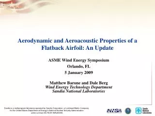
Aeroacoustics and Aerodynamic Performance of a Rotor with Flatback Airfoils 2010 European Wind Energy Conference Warsaw, Poland 23 April 2010 Matthew Barone, Josh Paquette Sandia National Laboratories, Albuquerque, NM Eric Simley University of Colorado, Boulder, CO Monica Christiansen Penn State University, State College, PA
Outline • Flatback Airfoils: Motivation and Introduction • Flatback Airfoil Wind Tunnel Tests • Field Tests of the BSDS Rotor • Modeling of Flatback Rotor Noise
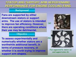
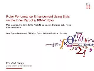
Motivation • Wind turbine blade design is a multi-disciplinary optimization problem • Cost of Energy is the ultimate objective function • Optimal aero-structural design may differ markedly from the optimal aerodynamic and optimal structural designs • Basic Design Question • Blade aerodynamics dominate the outboard design • Structural requirements dominate the inboard design • What inboard blade shape provides an optimal structural design without sacrificing too much aerodynamic performance?
Sandia Blade System Design Study (BSDS) • Employed a multi-disclipinary, iterative design process • Integrated blade design for aerodynamic performance, low weight, and manufacturability • Innovative blade design features • Flatback airfoils • Optimal design of a carbon fiber spar cap • 9 m blades were fabricated by TPI Composites for testing
Flatback Airfoils • Structural Advantages • Structural benefit of larger sectional stiffness for given chord and thickness. • Results in higher blade strength, lower blade weight. • Aerodynamic Advantages/Disadvantages • Sensitivity of lift to leading edge soiling is reduced. • Drag is increased (although L/D may still increase). • Increased aerodynamic noise due to blunt trailing edge.
Flatback Airfoil Research at Sandia Field Tests Wind Tunnel Tests Goal: Predict and Quantify Noise and Drag of Flatback Airfoils Computational Modeling
Wind Tunnel Experiments Facilities and Instrumentation • Virginia Tech Stability Wind Tunnel • Aeroacoustic test section • Beamforming microphone array • Airfoil surface pressure taps • Pitot tube wake surveys Tests Performed • DU97-W-300 and DU97-flatback (10% trailing edge thickness) • Flatback tested with/without splitter plate • Chord Reynolds numbers from 1.5 to 3.2 million • Several angles of attack
Wind Tunnel Noise Measurements U = 56 m/s • Findings from the wind tunnel tests • Flatback noise generated a prominent tone • Tonal frequency and amplitude is relatively insensitive to • Angle of attack • Boundary layer transition location • Simple splitter plate attachment reduced noise by ~12 dB
BSDS Blade Geometry flatback h c
Test Turbine and Instrumentation • Site • 8.7 m/s average wind speed at 80 m • Turbine • Modified Micon 65 • 19 m Rotor Diameter • 23 m Hub Height • Instrumentation • Inflow • Center and off-axis met towers, and nacelle • Wind speed and direction • Power • Loads • Tower, hub, and blade • Noise • 32-microphone array centered one hub height upwind USDA/SNL MiconTest Turbine
Acoustic Instrumentation Tower Microphone Array Schematic 45 Total Sensor Locations, configurable to either a low-frequency or high-frequency array. Low-frequency Microphone Ellipse High-frequency Microphone Ellipse
Acoustic Measurements Averaged Noise Maps at Different Blade Azimuth Positions 250 Hz – Entire Rotor 1250 Hz – Single Blade
Rotor Performance Model WTPerf Performance Model with CFD-generated airfoil tables
Modeling of Flatback Noise Source • Brooks, Pope, and Marcolini (BPM) model for blunt trailing edge noise • Empirical model based on wind tunnel measurements • Peak amplitude depends on the ratio of blunt trailing edge thickness to boundary layer thickness, h/d* . • BPM only had data for h/d* < 1. • Modified BPM model • Scaling with flow velocity and blade dimensions unchanged • Spectral shape function unchanged • Amplitude function modified based on Virginia Tech wind tunnel data – more applicable to large h/d* • Low-frequency directivity function used Observer Boundary Layer d* Turbulent Wake h Trailing Edge
Modeling of Rotor Noise • Blunt Trailing Edge Noise • Blade divided into span-wise sections • Local relative flow velocity obtained from WTPerf model • Modified BPM model applied for each section with a flatback airfoil • Inflow Turbulence Noise • Empirical model of Hubbard and Shepherd • Other airfoil self-noise sources are not currently considered • Turbulent boundary layer trailing edge • Laminar vortex-shedding • Separation Flatback Noise Source Low-frequency noise
BSDS Rotor Noise Predictions Rotor-averaged Noise spectra for a ground observer one hub height upwind Wind Speed = 8 m/s Wind Speed = 12 m/s
Utility-Scale Rotor Noise Predictions Rotor-averaged Noise spectra for a ground observer one hub height upwind • WindPACT 1.5 MW Reference Turbine • Rotor Diameter = 72 m • Hub height = 85.3 m • Wind Speed = 11 m/s • Blade Pitch = 2.6 deg. • Rotational Speed = 20 RPM
Summary • Flatback airfoil technology can lead to lighter, more efficient rotors • Flatback rotor noise is being measured in a subscale field test • Challenging due to competing hub noise • Noise associated with the blunt trailing edge of flatbacks has been studied using models informed by wind tunnel data • Existing BPM model may be over-conservative for flatback airfoil noise • Flatback airfoil noise is predicted to be lower than inflow turbulence noise for both the subscale BSDS rotor and a reference 1.5 MW rotor with flatbacks
Ongoing Work • Acoustically absorbing foam panels will be added to the test turbine nacelle • Attenuate hub noise • Isolate inboard blade noise • Splitter plate trailing edge attachment will be added to the BSDS blades. • Examine effects on performance and noise. BSDS blade with trailing edge splitter plate