Download
1 / 75
800 likes | 1.11k Views
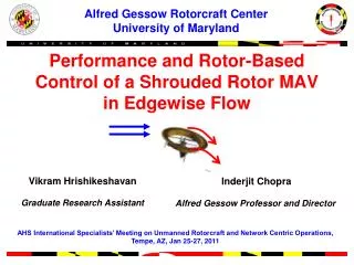
Alfred Gessow Rotorcraft Center University of Maryland. Performance and Rotor-Based Control of a Shrouded Rotor MAV in Edgewise Flow. Vikram Hrishikeshavan Graduate Research Assistant. Inderjit Chopra Alfred Gessow Professor and Director.

E N D
Alfred Gessow Rotorcraft Center University of Maryland Performance and Rotor-Based Control of a Shrouded Rotor MAV in Edgewise Flow VikramHrishikeshavan Graduate Research Assistant Inderjit Chopra Alfred Gessow Professor and Director AHS International Specialists’ Meeting on Unmanned Rotorcraft and Network Centric Operations, Tempe, AZ, Jan 25-27, 2011
Motivation Perimeter surveillance, building searches Rotor based MAVs - Hover capability - Maneuverability within confined spaces - Handle gust disturbances Need to study vehicle performance in adverse flow conditions and enable sufficient contrallability
Rotor Plane Main Vortex VortexSheet Main Vortex Wake Obstruction Low Reynolds Number Effects Re = 10,000-100,000 Increased profile drag Strong tip vortex Increased tip losses Low Re aerodynamics limits rotor performance
Performance Improvement : Shrouded Rotor • Reduces tip loss effects • Improves power loading • Protects rotor • Sturdy structure
Shrouded Rotor Performance 25 122 mm unshrouded rotor (FM ~0.6) More thrust for same power 20 No shroud 15 Mechanical Power (W) Shroud 10 5 0 0 50 100 150 200 250 300 Thrust (g)
1.8 Kg 0.3 Kg 115 Kg Weight 2 Kg 0.25 m 2.2 m Rotor diameter Shrouded Rotor Vehicles GTSpy Cypher
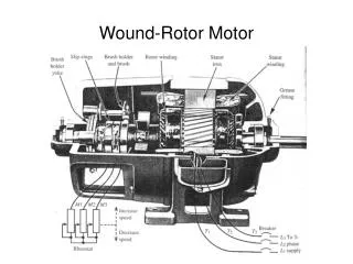
TiShrov – Shrouded Rotor MAV Weight 300 g Hingeless rotor (245 mm dia) Circular camber, sharp LE carbon/epoxy Driven by 75 W brushless outrunner motor Shroud (45 g) Carbon /epoxy Battery 3 cell 800mAH 20C LiPo IMU Complimentary filter gyro and acc input for pitch and roll attitude Vanes for anti-torque Two deflectable flaps for yaw control
Flight in Hover Flybar Flybarless
Response to Edgewise Flow Adverse pitch up tendency
Outline • Performance in edgewise flow • Strategies to improve controllability of shrouded rotor in edgewise flow • Flight tests
Shroud Design Circular inlet Elliptic inlet Elliptic inlet shroud – more hover efficient (Lakshminarayan,Baeder (2010)) - CFD
Hover Performance Measurement • 2% thickness (t/c) • 8-13% circular camber • Sharpened leading edge • 2: 1 Taper @ 80%R
Hover Performance Circular inlet shrouded rotor Elliptic inlet shrouded rotor 3%R tip clearance 10% improvement in power loading with elliptic inlet shroud
Edgewise Flow: Asymmetric Pressure Distribution Hover, no gusts Hover, edgewise gust
Forces in Edgewise Flow Thrust Pitching moment Drag
Measurement of Forces in Wind tunnel Unshrouded (open) rotor Circular inlet shrouded rotor Elliptical inlet shrouded rotor
Pitching Moment Measurement Open jet Wind tunnel Pitching moment measurement Bearings Drag load cell
Drag Measurement Edgewise flow Drag load cell Linear bearing
Thrust: Open Rotor 24 deg collective No change in thrust
Thrust: Elliptical Inlet Shrouded Rotor Thrust for each rotor relatively unaffected by low edgewise flow
Drag: Open Rotor Drag (g) 2 m/s 1 m/s
60 50 40 30 20 10 0 1500 2000 2500 3000 3500 4000 RPM Drag: Circular Inlet Shroud 2 m/s Drag (g) 1.7 m/s 1.3 m/s 1 m/s
Drag: Elliptic Inlet Shroud 2 m/s 1.7 m/s Drag (g) 1.3 m/s 1 m/s
Drag: Comparison Elliptic inlet shroud Circular inlet shroud 3300 RPM Drag (g) Open rotor Shrouded rotor drag-speed slope is much higher than open rotor
Projected Surface Area Elliptic inlet has more projected surface area in direction of flow Leads to more drag
Pitching Moment Circular inlet shroud Open rotor 2 m/s 1.7 m/s 2 m/s 1.3 m/s 1 m/s 1 m/s
Pitching Moment Elliptic inlet shroud 2 m/s 1.7 m/s 1.3 m/s 1 m/s
Pitching Moment: Comparison (3300 RPM) Elliptic inlet shroud Circular inlet shroud Open rotor 300-400% higher pitching moment than open rotor
Alleviate Pitching Moment Flaps Vents - Increased weight (flap actuators) - Structural integrity of shroud reduced - Complex control in free flight Use rotor with swashplate control
Rotor Control Hingeless, flybarless rotor Force response ~ 45 deg delay Rotor generates nose-down moment Swashplate transfers cyclic (10 deg max) Edgewise flow
Control Authority: No Edgewise Flow Open Rotor Total control moment (g-cm) 180 Control authority drops at higher collectives 220 280
Control Authority: No Edgewise Flow Total control moment (g-cm) Total control moment (g-cm) Elliptic inlet shroud Circular inlet shroud 180 240 240 180 300 300 Control authority increases quadratically with RPM Higher operating RPM -> Higher control authority
Comparison: No Edgewise Flow Elliptic inlet shroud Circular inlet shroud 80-100 % Open rotor
CFD study on MAV shrouded rotor (Lakshminarayan, Baeder 2010) Ratio of shroud thrust to total thrust Rotor blade location - Shroud thrust contribution increases as rotor collective increases - Most of shroud thrust at instant rotor passes a given azimuth
Shrouded Rotor Control Authority Control Authority = Mrotor+ MShroud +ve cyclic -ve cyclic Shroud augments rotor control authority
Control Authority in Edgewise Flow M2 (Nose-down moment) +ve cyclic -ve cyclic
Control Authority in Edgewise Flow (2 m/s) Operate rotor at lower collective to minimize control authority reduction
Elliptic inlet shrouded rotor: Increase in adverse pitching moment not equivalent to increase in control authority – more sensitive to edgewise flow Only circular inlet shroud considered in following sections What is the gust tolerance?
Gust Disturbance Response Pitot tube Open-jet wind tunnel Gimbal PID attitude control IMU
Gust Disturbance Response Pitch (rad) Gust ~ 2 m/s Can the tolerance be increased ?
L1 Increase Control Authority L2 1) Increase cyclic pitch () 2) Increase differential lift for a given cyclic pitch ()
Cyclic Pitch Magnitude old new 100 150
Cyclic Pitch Magnitude Shrouded rotor New 150 Old 100
Differential Lift L c More control moment - Increase L for a given Increase chord of the airfoil Does it depend on solidity and/or planform?
Blade Planforms (a) Original planform (b) Rectangular (c) Taper 140% chord (d) Rectangular 140% chord Measure instead of Tested with circular inlet shroud