Download
1 / 23
230 likes | 264 Views
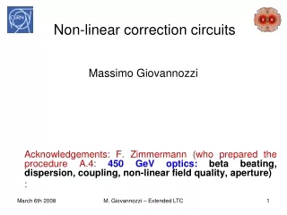
Comprehensive guide on non-linear correction circuits for optimizing field quality & tolerances in accelerator systems. Includes setting procedures, target tolerances, and measurement schemes. Contributions by Massimo Giovannozzi, F. Zimmermann, and M. Hayes.

E N D
Non-linear correction circuits Massimo Giovannozzi Acknowledgements: F. Zimmermann (who prepared the procedure A.4: 450 GeV optics: beta beating, dispersion, coupling, non-linear field quality, aperture) : M. Giovannozzi – Extended LTC
Families of non-linear corrector circuits • spool pieces: at dipole ends for b3, b4 and b5; powered differently per arc and per beam; total number of circuits 48 • lattice correctors: in the SSS for a3, b3, and b4; total number of circuits 112 • correction coils for triplet field errors: a3, b3, a4, b4, and b6; total number 40 In total, 200 independent correction circuits. M. Giovannozzi – Extended LTC
Circuits composition M. Giovannozzi – Extended LTC
Target and tolerances for observables These tolerances are reported in LHCPR 501 (by S. Fartoukh and O. Brüning). M. Giovannozzi – Extended LTC
Tolerances on spool pieces settings - I • Spool pieces are meant as local correctors of MBs field quality. • Tolerances on spool pieces settings analysed by M. Hayes (LHC PR 522 and 590). • 1 sigma reduction in DA corresponds to about 20%-40% mis-powering of ALL spool pieces. M. Giovannozzi – Extended LTC
Tolerances on spool pieces settings - II • In case of mis-powering of one single circuits the tolerances are looser. • Global or local correction with non-linear circuits can be envisaged. • Spool pieces are meant as local correctors of MBs field quality. • Tolerances on spool pieces settings analysed by M. Hayes (LHC PR 522 and 590). • 1 sigma reduction in DA corresponds to about 20%-40% mis-powering of spool pieces. M. Giovannozzi – Extended LTC
General measurement scheme • An off-centre orbit through a non-linear element generates a change of phase advance/tune given by • The off-centre orbit can be generated by: • Closed orbit bumps • Dispersion (by energy variation) • Tune measurement allows minimising the tune shift by using the non-linear correctors. • NB: in simulations the non-linear correctors are set according to differences between the approaches are of the order of 10%. M. Giovannozzi – Extended LTC
Expected dipole field quality at injection • In particular: • a3 component well-within tolerances, very likely correction is not required.
Procedures for setting non-linear correctors - I Prepared by F. Zimmermann with the help of S. Readelli Phases for full commissioning Stage A (pilot physics run) M. Giovannozzi – Extended LTC
Setting the b3 spool pieces - I Local correction (arc by arc) to within ~ 50% Proposed procedure (F. Zimmermann): • Pre-set spool pieces to values determined with FiDel (magnet measurements and model) • Adjust Q’ to ~2 units with the two families of lattice sextupoles • Check local correction with local dispersion bumps or groups of 7p bumps across individual arcs, octant by octant • Complementarily or additionally, measure off-momentum (chromatic) phase advance M. Giovannozzi – Extended LTC
Setting the b3 spool pieces - II Scheme by M. Hayes (LHC PR 522), O. Bruning (LHC PR 473) (Qx-Qy)+3 mm - (Qx-Qy)-3 mm vs. quality of correction Orbit with 7p bump across one arc; peak value of 3 mm Expected DQ~0.01 for 20% mis-powering of b3 spool pieces. Adjustment of b3 to within 10% is a reasonable target. M. Giovannozzi – Extended LTC
Setting the b3 spool pieces - III Simulated Df for dp/p=10-3 and dp/p=0 (machine as-built). Sector 7-8 features the smallest value of b3 at injection -> small effect 80% powering induces a variation on chromaticity of more than 2 units: Qx: 2 -> -0.7; Qy: 2-> 4.4 M. Giovannozzi – Extended LTC
Setting the b3 spool pieces - IV One missing circuit can be easily detected. M. Giovannozzi – Extended LTC
Setting the skew sextupole a3 - I Some facts: And: Tolerance on this effect: Considering the measured field quality, the tolerances are largely met (the MSS where considered not necessary since Day 1 according to the analysis presented at Chamonix XV)! where M. Giovannozzi – Extended LTC
Setting the skew sextupole a3 - II • Proposed procedure (global approach): • check with off-momentum closest tune approach • Tolerance to meet: M. Giovannozzi – Extended LTC
Setting the b4 spool pieces - I • Global correction to within ~ 30% • Proposed procedure (F. Zimmermann): • Leave lattice octupoles switched off • Separate tunes (to reduce contribution from a3, if needed) • Pre-set spool pieces to values determined with FiDel (magnet measurements and model) • Measure Q’’ vs. b4 and set b4 by minimising Q’’ • Verify detuning with amplitude • Considering the measured field quality, the tolerances are met (the MCO where considered not necessary since Day 1 according to the analysis presented at Chamonix XV)! M. Giovannozzi – Extended LTC
Setting the b5 spool pieces - I • Local correction (arc by arc) to within ~ 50% • Proposed procedure (F. Zimmermann): • First minimize Q’’’ (global) • Measure off-momentum detuning with amplitude; without any correction expect DQ~10-3 at 3s and d=10-3 (8x smaller for single arc) • Complementarily, measure chromatic phase advance (effect could be difficult to detect) • Measure resonant driving terms (option) • Varying kicks to obtain “frequency map’’ (option) M. Giovannozzi – Extended LTC
Setting the b5 spool pieces - II [F. Zimmermann, Chamonix03] Huge global effect of b5. simulated Df for 1s kick for dp/p=10-3 and dp/p=0; 3 cases: (1) no spool piece mis-powered, (2) sextupole circuit KCS45 missing (BPMs 194 to 257), (3) decapole circuit KCD45 missing we can detect missing b3 circuits, but not missing b5! M. Giovannozzi – Extended LTC
Setting the b4(f, d) correctors - I • The Landau octupoles will be used only with higher intensities or with special configurations (TOTEM beam with 156 might be unstable). • The polarity should be checked arc by arc for each family. • Proposed procedure: • Switch on a single family • Set it to about 10%-20% of its nominal strength • Measure Q’’ (it depends linearly on b4, hence the sign is visible) M. Giovannozzi – Extended LTC
Setting the b4(f, d) correctors - II M. Giovannozzi – Extended LTC
Non-linear correctors in low-beta triplets • The non-linear correctors will not be needed until b* < 1 m (from numerical simulations). Hence, they will not be needed for the Phase A. • Procedure to set them to be specified. • A good candidate is the use of IR bumps as it was done in RHIC (J.-P. Koutchouk et al. PAC01, inspired by LEP coupling measurements – 1990.) M. Giovannozzi – Extended LTC
Conclusions • Spool pieces: • Procedure defined: • b3: correction (local) required and feasible • b4: correction (global) probably not required • b5: correction (global) required. Local difficult… • MSS: • Procedure defined, but correction not needed • MO: • Polarity measurement defined: easy to do. • Low-beta triplet correctors: • Correction not needed for Phase A. Strategy known (IR bumps): to be studied in our case Next step: possible implementation in the on-line model? M. Giovannozzi – Extended LTC