Download
1 / 42
420 likes | 455 Views
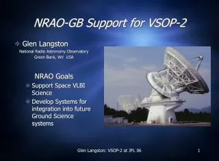
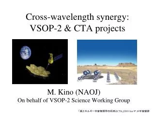
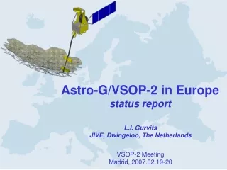
VSOP-2 Link System. National Astronomical Observatory of Japan Yusuke Kono. Outline. Onboard Link system update General over view Ka-band OBS frequency changed Frequency selection Downlink 37.5GHz or 26GHz? The common design of Tracking station. Observation System. Observation Frequency

E N D
VSOP-2 Link System National Astronomical Observatory of Japan Yusuke Kono
Outline • Onboard Link system update • General over view • Ka-band OBS frequency changed • Frequency selection • Downlink 37.5GHz or 26GHz? • The common design of Tracking station
Observation System Observation Frequency Q-band: 41 - 45 GHz K-band: 20.6- 22.6 GHz X-band: 8.0 - 8.8 GHz Intermediate 6.6- 8.8 GHz Base Band 1.3 GHz Q-band (R) LNA × LO (36/34GHz) ~ Q-band (L) LNA × × K-band (R) LNA × MOD ADC DF IF-SWITCH (6 to 2 ) LO (29.2GHz) ~ Ka-TX Synthesizer × K-band (L) LNA × ADC DF 1024Mbps Synthesizer VLBI DATA Rate: 512/256 Msps Bit: 1/2 bit Channel: 2 ch X-band (R) LNA X-band (L) LNA GRT: 512Msps(2bit) or 256Msps(2bit) expected
Ka Antenna • Diameter 80cm • Efficiency 70 % • WaveGuide&Rotary Joint • TWTA(20W) inside • 60W power consumption • radiated through a heat pipe to space
Link frequency selection : Frequency Allocation • Uplink • Three Space Research bands in 13~17GHz are hopeless (JAXA Frequency room) • 13.25-14.3 GHz , 16.6 - 17.1 GHz ,17.2-17.3. GHz • Uplink is 40 GHz • Downlink • 26GHz and 37.5 GHz possible • 26 GHz band will be heavily used by the time that VSOP-2 is launched. Many missions are being planned for this band including NASA's Lunar Exploration Missions, some L1 and L2 missions like JWST, and some wideband low Earth orbiters like NOAA's NPOESS. Most of these missions will receive higher priority than VSOP-2 if there is a need for coordination. • 37.5 GHz is wide open and there won't be any need for coordination or worries about interference to VSOP-2 or from VSOP-2 to other missions.
Link frequency selection : Ionoshphere • VSOP-2 OBS/link simulation (by Dr.Asaki) • Software: ARIS • MS-TID (Medium Scale Traveling Ionospheric Disturbance) ~0.2TECU • Zenith TEC bias error~6 or 60 TECU • Conclusion • Ionosheric effect of 37.5GHz is smaller than 26GHz • Tropospheric error in fringe phase of VLBI observation is outstanding. • 40/26 and 40/37.5 GHz system possible
Onboard Lo-Phase(Zenith TEC Bias : 6 TECU) 40GHz/26GHz 40GHz/37GHz 43GHz: 15.0 deg 22GHz: 7.9 deg 43GHz: 1.9 deg 22GHz: 1.0 deg Black: 43GHz Red: 22GHz
Space-VLBI Fringe Phase(MS-TID , Zenith TEC Bias : 60 TECU) 60 min (Tropospheric and Ionospheric Errors) 40GHz/26GHz 40GHz/37GHz Black: 43GHz Red: 22GHz
No difference No difference 43GHz Coherence 22GHz Coherence
Link frequency selection : Link margin • ------------------------------------------------------ • Link design 26GHz 37.5GHz d(26-37.5) • ------------------------------------------------------ • TX Gain dB 45.2 48.4 -3.2 • Feed Loss dB -4.2 -5.5 1.3 • Space LossdB -210.3 -213.4 3.2 • Rain Loss dB -4.6 -8.1 3.5 • Atm Loss dB -1.7 -2.2 0.5 • RX Gain dB 64.9 67.2 -2.3 (AE 34, 42%) • Tsys dB -23.7 -24.6 0.9 • ------------------------------------------------------ • Total dB 3.9
Rain condition of UDSC One-hour rainfall data at Usuda deep space center Nov.9,2005- Nov.9,2006 Time (2mm/h) is 2% of time!
Interference of 26GHz to K-band LNA Less than -60 dBm (Tx 20W, Off-beam interference, space loss) < LNA saturation level +9dBm
Technical easiness • 26 / 40GHz • Wider frequency range than waveguide and waveguide Rotary joint frequency specification (26.5-40 GHz) • More complicated Ka-ant system • Setting TX-HPA at the top of the boom is not good for thermal control
Link frequency selection: summary • The downlink of 26GHz has several attractive merits comparing with 37.5 GHz. But, • It is too severe to get the 26 GHz band allocation • 40/26GHz link will increase complexity of the onboard system • Construction cost of the s/c same • 40/37GHz link is also feasible • The downlink of 37.5 GHz proposed
The common design of Tracking station • Based on Halca method • NRAO GB project book
Functional requirement 1 • Radio links to s/c • Astronomical data downlink • Time transfer uplink • Time transfer downlink • Realtime signal Processing • Astronomical data • Time transfer
Functional requirement 2 • Interface • From mission operation • From orbit determination center • To correlation center • To orbit determination center • To mission operation
Functional requirement 3 • Automation • Normal operation • Recovery from link dropout • Recovery after station power failure
System design 1 • Main antenna • Feed and Optics • RF subsystem • Wideband data subsystem • Two way timing • Reference distribution • Control and monitoring
System design 2 • Design principles • Compact design • Careful choice of reference signals • Wideband design • Avoidance of ALC loops • Use of exiting design whenever possible • Built-in test facilities and monitoring
System design 5 • Required Dynamic range • Packaging and cabling
Required basic function of Onboard link system • Data transmission • 1024 Mbps QPSK, Diff.Enc • 37.5 GHz, 20 Watt (-2dB Backoff) • EIRP 83.9 dBm • 80cm HGA, RHCP • TLM (bitrate TBD) data merged • Coherent transponder • Uplink carrier receiver
Required basic function for tracking station 1 • Standard clock transfer • Uplink transmission • Carrier of 40GHz, EIRP 93.5 dBm, RHCP • Downlink carrier recovery • Carrier of 37.5GHz, RHCP • Measurement of phase difference between up and downlink • DeltaT correction file output • Doppler compensation by prediction
Required basic function for tracking station 2 • Data downlink demodulation • 37.5 GHz QPSK, RHCP • Required BER 1E-2 • Data and carrier recovery • Data storage • Data Storage • 1024Mbps, 11 T Byte / 24h • VSI-H&S compatibility (for correlators) • Realtime/quasi-realtime TLM QL
Principles of BER • The cross-correlation SNR or sensitivity of the spacecraft data (with transmission errors) against ground telescope data (no quantization bit errors) is degraded by the BER loss factor • VSOP is designed for BER = 5E-4, so its factor is negligible. • The calibrated sensitivity loss for the best ground radio telescope is taken to be 2% (0.980). • Correspondingly, BER = 1E-2. • Designing for BER = 1E-2 is a strictly worst-case condition. Most of the time the BER will be much lower. Springett 2002
~ VSOP-2 Ground System Feed U/C TX GEN O/E E/O LOGEN O/E E/O Doppler Cntr / meas. Feed D/C O/E Demodulator E/O Operation Center Antenna Room
~ ~ Operation Center TX GEN 1.54GHz+fud 1.5GHz 1.5GHz REF GEN LPF D/A 100MHz E/O SW BPF NCO Fo (nominal) DIFF ENC DATA GEN 5MHz 5MHz STD CLK D/A LPF GPS 1.5GHz Doppler Control Meas. DOP CONT UP Fup (PREDICT) 1pps TIMEDEC E/O 100MHz Time DOP CONT DW Fdw (PREDICT) Doppler Control PC Copper Count Dop.Cnt Demodulator Control PC 1.5GHz NCO Remote station LPF A/D TI COUNT 1.54GHz+fdd BPF NCO BIT SYNC DIFF ENC FRAME SYNC VSI I/F O/E Storage PD BER MEAS A/D LPF 1.5GHz
Antenna Room POWER METER 4.388+fud GHz 1.54+fud GHz ATT BPF BPF O/E 40.288 + fud GHz HPA 2.848GHz 35.9 GHz 100MHz 2.848GHz X 2828 /1000 O/E Feed DIP BPF HYB X 359 Translator 37.440 + fdd GHz 35.9 GHz LNA 1.54+fdd GHz BPF BPF O/E Antenna Room
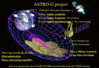
ASTRO-G Ka-Band Link Simulations • Uplink / Downlink • 40GHz / 26GHz • 40GHz / 37GHz • Effects of the onboard local phase due to the ionosphere • ARIS simulations • MS-TID (Medium Scale Traveling Ionospheric Disturbance) • Zenith TEC bias error
Discussion • TLM Header • Realtime/Quasi-realtime • Mobile TX simulator • Phase Detection method • VLBI Data storage • VSI I/F • MarkVB • RVDB of Japan • Data transportation • PM TEST and schedule
2-way Link: the effect of the ionosphere Δφion N : TEC [el./m2] fobs : Observing frequency [GHz] fup : Uplink frequency [GHz] fdown:Downlink frequency [GHz] c : Velocity of light [m/s]
Ka Tracking Simulations Black : Usuda Red : Goldstone Blue : Tidbinbilla Pink : Hart Yellow: Malind
Onboard Lo-Phase(Zenith TEC Bias : 60 TECU) 40GHz/26GHz 40GHz/37GHz 43GHz: 62.5 deg 22GHz: 45.8 deg 43GHz: 17.9 deg 22GHz: 9.3 deg Black: 43GHz Red: 22GHz
Onboard Lo-Phase(Zenith TEC Bias : 6 TECU) 40GHz/26GHz 40GHz/37GHz 43GHz: 15.0 deg 22GHz: 7.9 deg 43GHz: 1.9 deg 22GHz: 1.0 deg Black: 43GHz Red: 22GHz
Space-VLBI Fringe Phase(MS-TID , Zenith TEC Bias : 60 TECU) 60 min (Tropospheric and Ionospheric Errors) 40GHz/26GHz 40GHz/37GHz Black: 43GHz Red: 22GHz
No difference No difference 43GHz Coherence 22GHz Coherence
Principles of Link Design • But extremes for these conditions are very rarely concurrent, so most of the time there will be a substantial excess of performance (a positive link margin of many dB). This is excessive design, a waste of link resources. • A statistical link design methodology reflects the fact that temporal variation of the parameters rarely results in simultaneous worst-case extremes. Springett 2002