RPC Electronics Link system
RPC Electronics Link system. RPC Annual Review, CERN, June 13, 2006 Maciek Kudla for Lappeenranta and Warsaw University. RPC Electronics - overview. Link system. Link system control. Link system - tasks. Control of FEBs (thresholds etc), Synchronization FEB data to LHC clock,

RPC Electronics Link system
E N D
Presentation Transcript
RPC ElectronicsLink system RPC Annual Review, CERN, June 13, 2006 Maciek Kudla for Lappeenranta and Warsaw University
RPC Electronics - overview Link system Link system control Maciek Kudla, RPC Review – Link System 13.06.2006
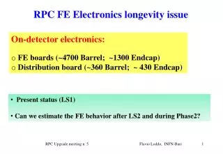
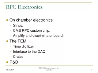
Link system - tasks • Control of FEBs (thresholds etc), • Synchronization FEB data to LHC clock, • Transmission FEB data (compressed) to Trigger Boards via optical links, • Diagnostic readout (RPC histograms, events) via CCU rings and CCS boards, • Injection of test patterns at FEB and LB level. Maciek Kudla, RPC Review – Link System 13.06.2006
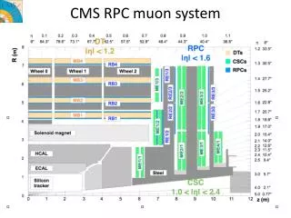
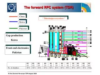
Link system – on detector Electronics Inventory Staged: all RB and RE1, RE2, RE3 < 1.6; no RE4, RE5 Maciek Kudla, RPC Review – Link System 13.06.2006
Link Board Box – front view Link and Control Boards compartment Maciek Kudla, RPC Review – Link System 13.06.2006
Link Board Box – back view Detector cables (data, control) come here Maciek Kudla, RPC Review – Link System 13.06.2006
Link Board Box – with all boards ... Working in 904 Integration Area Maciek Kudla, RPC Review – Link System 13.06.2006
Link Board Signals from RPC Detector Optical output (trigger) Maciek Kudla, RPC Review – Link System 13.06.2006
Control Board Control Signals to RPC Detector Optical input/output (control) Xilinx mezzanine board to be replaced by Actel FPGA Maciek Kudla, RPC Review – Link System 13.06.2006
LBB - Frontplane Control Bus between LBs and CB Maciek Kudla, RPC Review – Link System 13.06.2006
Control/Readout Crate - CCS Board 3 CCS FEC Boards drives 18 CCU rings Maciek Kudla, RPC Review – Link System 13.06.2006
MTCC – Link system • Detector: (installed) • YE+1 - 2 LBBs, • YB+2 - 2 LBBs, • YB+1 - 1 LBB; • Green barack: (installed) • Control/Readout Crate (1 CCS, 1 DCC), • Trigger Crate (1 TB), • TTC Crate (TTCci, LTC, TTCex); • 904: (installed, used for software development) • 2 LBB, • Control/Readout Crate (1 CCS, 1 DCC), • Trigger Crate (1 TB), • TTC Crate (TTCci, LTC, TTCex); Maciek Kudla, RPC Review – Link System 13.06.2006
Link system - Status and schedule • LBB - 36 installed on detector, 17 ready for installation, • 43- to be assembled, • LB - 55 used MTCC, 6 used 904, 400 to be delivered July, • CB - 8 used MTCC, 3 used 904, 60 to be delivered July, • FP - 8 used MTCC, 3 used 904, 60 to be delivered July, • Control Crate - 1 for MTTC, one for software development in 904 Maciek Kudla, RPC Review – Link System 13.06.2006
ProductionTests of LBB components • Step 1 - Factory - basic tests (to assure the production quality and speed-up repair work): • LB tested with the production Lappeenranta tester • all outside connections are covered, • all connections between Xilinxes, • QPLL locking; • CB tested with BSCAN • some of the outside connector, • all connection between chips with BSCAN support, • possibly the flash programming (?); • Step 2 – Lappeenranta - "system, functional test" full crate assemblied (2xCB, 18LB, 2FB): • test boards used instead of FEBs, • this should cover the things that are not included in Step 1 • CB outside connections, • flash programming; • Step 3 – 904 - Commissioning: • LBs, CBs in full ring setup – Step 2 .1 repeated ~1 hour needed Maciek Kudla, RPC Review – Link System 13.06.2006
RPC Link system Integration Status • All tasks: • Control of FEBs (thresholds etc), • Synchronisation FEB data to LHC clock, • Transmission FEB data (in compressed form) to Trigger Boards via optical links • Diagnostic readout (RPC histograms, events) via CCU rings, • Injection of test patterns at FEB and LB level • Tested in several tests runs and in 904 Integration Area • i.e • synchronisation quality very good (< 1ns), • Long CCU chain with redundacy tested, etc Maciek Kudla, RPC Review – Link System 13.06.2006
Summary • System in production stage, • Software development advanced (see Bunkowski’s talk), • Heavy cabling and detector installation before us... Maciek Kudla, RPC Review – Link System 13.06.2006