Atomic Absorption Spectroscopy
Atomic Absorption Spectroscopy. Lecture 15. Emission in Flames.

Atomic Absorption Spectroscopy
E N D
Presentation Transcript
Atomic Absorption Spectroscopy Lecture 15
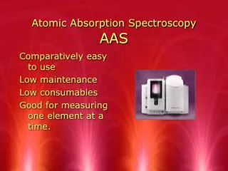
Emission in Flames There can be significant amounts of emission produced in flames due to presence of flame constituents (molecular combustible products) and sometimes impurities in the burner head. This emitted radiation must be removed for successful sensitive determinations by AAS, otherwise a negative error will always be observed. We can visualize this effect by considering the schematic below:
The detector will see the overall signal which is the power of the transmitted beam (P) in addition to the power of the emitted radiation from flame (Pe). Therefore if we are measuring absorbance, this will result in a negative error as the detector will measure what it appears as a high transmittance signal (actually it is P + Pe). In case of emission measurements, there will always be a positive error since emission from flame is an additive value to the actual sample emission. It is therefore obvious that we should get rid of this interference from emission in flames.
Absorbance is defined as: A = log (Po/P) However, in absence of a sample the detector will measure S1 , where: S1 = Po + Pe In presence of a sample, the detector will measure S2, where: S2 = P + Pe Therefore A = log (Po + Pe)/(P + Pe) At high absorbances, Pe may become much larger than P and the absorbance will be a constant since both Po and Pe are constants: A = log (Po + Pe)/(Pe)
Source Modulation It turned out that excluding the emission signal from flames can easily be done by an addition of a chopper to the instrumental design. The chopper is a motor driven device that has open and solid (mirrors in some cases) alternating regions as in the schematic:
The function of the chopper is to chop the light leaving the source so that when the incident beam hits the chopper at the solid surface, the beam will be blocked and detector will only read the emitted signal from the flame. As the chopper rotates and the beam emerges to the detector, the detector signal will be the sum of the transmitted signal plus that emitted from the flame. The signal processor will be able to subtract the first signal from the second one, thus excluding the signal from emission in flames.
This can be represented by the following equations, in presence of a sample: Signal 1 (Blocked Beam) = Pe Signal 2 (Transmitted Beam) = P + Pe Overall Difference Signal = (P + Pe) - Pe = P (Corrected Signal) This correction method for background emission in flames is called source modulation.
The schematic of the AAS instrument with source modulation correction can be represented by the following schematic:
It should be recognized that addition of extra components to an instrument will decrease the signal to noise ratio and addition of a moving component is usually regarded as a disadvantage due to higher need for maintenance. Another procedure which can overcome the emission from flames is to use a modulated power supply that will give fluctuating intensities at some frequency (say for example pulsed radiation at a specific frequency).
The emission from flames is a continuous signal but that from the source is modulated. Now if we use a high pass RC filter, only the fluctuating signal will be measured as signal while the DC signal will be considered zero as it can not pass through the electronic filter. The high pass RC filter is a device which uses a resistor and a capacitor the impedance of which is inversely proportional to the frequency of the modulated signal. Therefore, only high frequencies will have low impedance and can pass through the capacitor while signals of low frequencies will suffer very high resistance and will not be able to go through the capacitor.
AAS Instruments Instruments in AAS can be regarded as single or double beam instruments. Single Beam Atomic Absorption Spectrophotometers A single beam instruments is the same as the one described above (source modulation section) or generally:
The term “spectrophotometer” implies that the instrument uses a dispersive monochromator (containing a prism or a grating). Also, the detector is a photomultiplier tube in most cases.
Double Beam Atomic Absorption Spectrophotometers In this type of instruments, the incident beam is split into two beams of equal intensity by a chopper with the solid surface being a mirror. One of the beams will traverse the sample in the atomizer while the other is considered as a reference. Detector signals will be consecutive readings of both the reference and sample beams. The ratio of the reference to the sample beams is recorded to give the final signal.
A schematic representation of a double beam instrument is shown below:
It should be emphasized here that in the absence of sample, Pr is not equal to Po since the reference beam traverses through air while the other beam traverses through the flame. In flames, particulates and molecular species scatter and absorb a portion of incident radiation, which results in a lower intensity of the beam. To act as a real double beam, The AA spectrophotometer reference beam should pass through a reference flame.
But even if we do that, there are no guarantees that both beams will be of equal intensities because it is almost impossible to obtain exactly equivalent flames. It is therefore important to understand that the excellent features of a double beam configuration are not achievable in AAS instrumentation.
Interferences in Atomic Absorption Spectroscopy There are two major classes of interferences which can be identified in atomic absorption spectroscopy. The first class is related to spectral properties of components other than atomized analyte and is referred to as spectral interferences. The other class of interferences is related to the chemical processes occurring in flames and electrothermal atomizers and their effects on signal. These are referred to as chemical interferences and are usually more important than spectral interferences.
Spectral Interferences 1. Spectral line Interference Usually, interferences due to overlapping lines is rare since atomic lines are very narrow. However, even in cases of line interference, it can be simply overcome by choosing to perform the analysis using another line that has no interference with other lines. Therefore, line interference is seldom a problem in atomic spectroscopy.