Download
1 / 107
1.09k likes | 1.16k Views
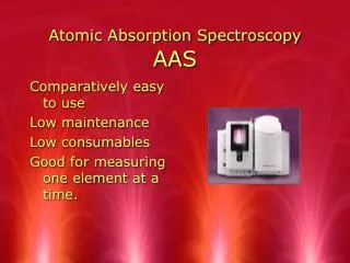
Learn about flame atomization techniques in AAS, including flame atomizer types, burner design, fuel-oxidant ratios, and performance characteristics. Understand how different elements require specific flame conditions for accurate analysis.

E N D
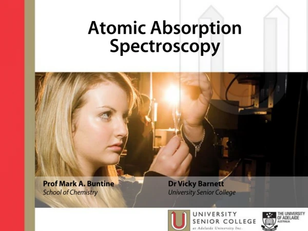
Atomic Absorption Spectroscopy Lecture 13 1
Flame Absorbance profiles The temperature of a flame depends on the position from its tip. • So, it is necessary to concentrate our work on one spot in a flame and preferably adjust the height of the flame to get best signal. • In fact, not all elements require a specific height above burner tip but rather each element has its own requirements which largely reflect some of its properties. • For example: For Silver (Ag) analysis: Using higher distances from the tip so that higher temperatures are achieved to analyze for silver. This is possible since silver will not be easily oxidized.
For Chromium analysis: Occurs at lower heights (fuel rich flames) since at higher heights oxygen from atmosphere will force chromium to convert to the oxide which will not be atomized at flame temperatures. For magnesium analysis: Increasing the height above tip will increase the signal due to increased atomization at higher temperatures. However, at higher distances the oxide starts to form leading to a decrease in signal.
Flame Atomizers (Continuous Atomizers) There are several types of flame atomizers available. 1) The turbulent flow burner: The simplest type that is very similar to conventional Bunsen burner. Disadvantages: • This type of burner suffers from fluctuations in temperature since there is no good mechanism for homogeneous mixing of fuel and oxidant. • The drop size of nebulized sample is also inhomogeneous which adds to fluctuations in signal. • The path length of radiation through the flame is small which suggests a lower sensitivity of the technique. • Turbulent flow burners are also susceptible to flashback.
2) Laminar flow burner (also called premix burner): The drawbacks of the turbulantburnaer are overcome using this most widely used burner. Advantages: • Quite flames obtained. • Long path length are obtained. • Flashback is avoided. • Very homogeneous mixing between fuel, oxidant, and droplets take place. • Larger droplets are excluded and directed to a waste container.
Fuel and Oxidant Regulators The adjustment of the fuel to oxidant ratio and flow rate is undoubtedly very crucial. 1) Stoichiometric ratios are usually required. 2) Optimization is necessary in order to get highest signal. In the determination of metals that form stable oxides: A flame with excess fuel is preferred in order to decrease oxide formation.
Performance Characteristics of Flame Atomizers • Reproducibility of flame methods are usually superior to other atomization techniques. • However, the residence time of an atom in a flame is in the order of 10-4 s which is very short. This is reflected in a lower sensitivity of flame methods as compared to other methods. • Also, conventional flames with reasonable burning velocities can produce relatively low temperatures which make them susceptible to interference from molecular species.
2. Electrothermal Atomization Advantages: These have better sensitivities than flame methods. Explained by: • A longer atom residence time is achieved (can be more than 1 s). • Also, atomization of the whole sample in a very short time. Procedure: As the name implies, a few mL of the sample are injected into the atomization chamber (a cylinder of graphite coated with a film of pyrolytic carbon).
Electrothermal Atomization processes: • Evaporation: The solvent associated with the sample is evaporated in a low temperature (~120 oC) slow process (seconds). b. Ashing: Sample is ashed to burn organics associated with the sample at moderate temperatures (~600 oC, seconds). c. Atomization: The current is rapidly increased after ashing so that a temperature in the range from 2000-3000 oC is obtained in less than1 second.
Electrothermal Atomizers (Discrete Atomizers) The cylindrical graphite tube: • The heart of the atomizer. • Contain efficient heating elements and electronics. • Cylindrical graphite tube opened from both ends and has a central hole for sample introduction. What type of Graphite: It was found that porous graphite results in poor reproducibility since some of the analyzed materials will diffuse through porous graphite and will thus lead to a history effect.
Pyrolytic graphite :النوع المفضل The cylindrical graphite is made from a special type of nonporous high quality graphite. Description: • The length of the cylinder is 2-5 cm. • The diameter is less than 1 cm. • When the tube is fixed in place electrical contacts are achieved which are water cooled. • Two inert gas streams (argon) flow at the external surface and through the internal space of the tube to prevent oxidation and clean the tube after each measurement. • Usually, samples are analyzed in triplicates where three consecutive reproducible signals are required for each sample.
Atomic Absorption Spectroscopy Lecture 14
Performance Characteristics of Electrothermal Atomizers Advantages: • Electrothermal atomization is the technique of choice in case of small sample size. • Higher sensitivities than flames are ordinarily obtained. Disadvantages: • The analysis time is in the few minutes range. • The relative precision is in the range of 5-10% as compared to 1% in flame methods. • In addition, the linear dynamic range is usually small (~ two orders of magnitude) which requires extra sample manipulation. • It may be also mentioned that better experienced personnel can achieve the merits of the technique.
Atomic Absorption Instrumentation Atomic absorption instruments consist of: 1) A source of radiation. 2) A monochromator. 3) A flame or electrothermal atomizer in which sample is introduced. 4) and a transducer.
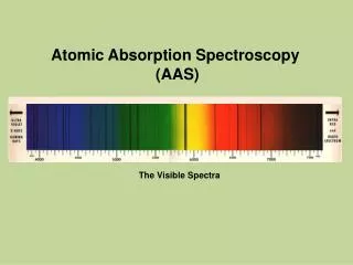
1) Radiation Sources • Radiation in the UV-Vis region is required. • We can not use broad band sources. Because: • The best monochromators can not provide a bandwidth that is narrower than the atomic absorption line. • If the bandwidth of the incident radiation is wider than the line width, measurement will fail as absorption will be only a tiny fraction of a large signal which is difficult to measure and will result in very low sensitivities (Figure a). • Therefore, line sources with bandwidths narrower than that of the absorption lines must be used.
X
This can be achieved by using a lamp producing the emission line of the element of interest where analyte atoms can absorb that line. • Conditions are established to get a narrower emission line (from lamp) than the absorption line. • This can in fact be achieved by getting an emission line of interest at the following conditions:
Conditions for getting an emission line of interest: • Low temperatures: To decrease Doppler broadening (which is easily achievable since the temperature of the source is always much less than the temperature in flames). 2. Lower pressures: This will decrease pressure broadening and will thus produce a very narrow emission line.
Difficulty: • Separate lamp for each element is neede for a which is troublesome and inconvenient. Overcome: • However, recent developments lead to introduction of multielement lamps. Requirement: • In this case, the lines from all elements should not interfere and must be easily resolved by the monochromator so that, at a specific time, a single line of one element is leaving the exit slit .
Types of Line sources:1)Hollow Cathode Lamp (HCL) • This is the most common source in atomic absorption spectroscopy. • It is formed from a tungsten anode and a cylindrical cathode the interior surface of which is coated by the metal of interest. • The two electrodes are usually sealed in a glass tube with a quartz window and filled with argon at low pressure (1-5 torr). • Ionization of the argon is forced by application of about 300 V DC where positively charged Ar+ heads rapidly towards the negatively charged cathode causing sputtering. • A portion of sputtered atoms is excited and thus emit photons as atoms relax to ground state. • The cylindrical shape of the cathode serves to concentrate the beam in a limited region and enhances redeposition of sputtered atoms at the hollow surface.
Properties: • High potentials usually result in high currents which, in turn, produce more intense radiation. • However, Doppler broadening increases as a result. • In addition, the higher currents will produce high proportion of unexcited atoms that will absorb some of the emission beam which is referred to as self absorption (a lower intensity at the center of the line is observed in this case).
1) Electrodeless Discharge Lamps (EDL) • Is a sealed quartz tube containing a few torr of an inert gas and a small quantity of the metal of interest. • Excitation of the metal is achieved by a radiofrequency or a microwave powered coil through ionization of argon, due to high energetic radiofrequency. • Ionized argon will hit the metal causing excitation of the atoms of the metal of interest. • The output power of the EDL lamp is higher than the HCL lamp. • However, compared to HCL lamps, EDL lamps are rarely used.
Emission in Flames There can be significant amounts of emission produced in flames: due to • Presence of flame constituents (molecular combustible products). • Sometimes impurities in the burner head. This emitted radiation must be removed for successful sensitive determinations by AAS. • What happened If it not removed?? 1) In case of absorption measurments: A negative error will always be observed. We can visualize this effect by considering the schematic below:
The detector will see the overall signal: Which is the power of the transmitted beam (P) in addition to the power of the emitted radiation from flame (Pe). Therefore if we are measuring absorbance, this will result in a negative error as the detector will measure what it appears as: A high transmittance signal (actually it is P + Pe).
Explanation: Absorbance is defined as: A = log (Po/P) However, in absence of a sample the detector will measure S1 , where: S1 = Po + Pe In presence of a sample, the detector will measure S2, where: S2 = P + Pe Therefore A = log (Po + Pe)/(P + Pe) At high absorbances, Pe may become much larger than P and the absorbance will be a constant since both Po and Pe are constants: A = log (Po + Pe)/(Pe)
2) In case of emission measurements: • Here will always be a positive error since emission from flame is an additive value to the actual sample emission. • It is therefore obvious that we should get rid of this interference from emission in flames.
Correction method for background of flame emission Source Modulation For excluding the emission signal from flames can easily. 1) Can be done by an addition of a chopper to the instrumental design. What is the chopper: The chopper is a motor driven device that has open and solid (mirrors in some cases) alternating regions as in the schematic:
The function of the chopper: Is to chop the light leaving the source so that when the incident beam hits the chopper at the solid surface, the beam will be blocked and detector will only read the emitted signal from the flame. As the chopper rotates and the beam emerges to the detector, the detector signal will be the sum of the transmitted signal plus that emitted from the flame. The signal processor will be able to subtract the first signal from the second one, thus excluding the signal from emission in flames.
Beam chopper for subtracting flame background emission • Lamp and flame • emission reach detector • Only flame • emission reaches • detector (c) Resulting signal
This can be represented by the following equations: Signal 1 (Blocked Beam) = Pe Signal 2 (Transmitted Beam) = P + Pe Overall Difference Signal = (P + Pe) - Pe = P (Corrected Signal) This correction method for background emission in flames is called source modulation.
The schematic of the AAS instrument with source modulation correction can be represented by the following schematic:
It should be recognized that addition of extra components to an instrument will decrease the signal to noise ratio and addition of a moving component is usually regarded as a disadvantage due to higher need for maintenance. 2) Another procedure: Which can overcome the emission from flames is to use a modulated power supply that will give fluctuating intensities at some frequency (say for example pulsed radiation at a specific frequency).
The emission from flames is a continuous signal. • But that from the source is modulated. Now if we use a high pass RC filter, only the fluctuating signal will be measured as signal while the DC signal will be considered zero as it can not pass through the electronic filter. The high pass RC filter: • Is a device which uses a resistor and a capacitor the impedance of which is inversely proportional to the frequency of the modulated signal. • Therefore, only high frequencies will have low impedance and can pass through the capacitor while signals of low frequencies will suffer very high resistance and will not be able to go through the capacitor.
AAS Instruments Instruments in AAS can be regarded as 1) Single or 2) double beam instruments. 1) Single Beam Atomic Absorption spectrophotometers. A single beam instruments is the same as the one described above (source modulation section) or generally:
The term “spectrophotometer” implies that: 1- The instrument uses a dispersive monochromator (containing a prism or a grating). 2) Also, the detector is a photomultiplier tube in most cases.