Single Phase On-Line UPS Demo Using MC9S12E128
660 likes | 981 Views
Single Phase On-Line UPS Demo Using MC9S12E128. UPS Classification. Based on the topology the UPSes are classified to the three basic categories (IEC 62040-3): Passive Standby (Off-line) Line-interactive Double Conversion (On-Line). Basic UPS Topology - Off-line UPS. Advantages:

Single Phase On-Line UPS Demo Using MC9S12E128
E N D
Presentation Transcript
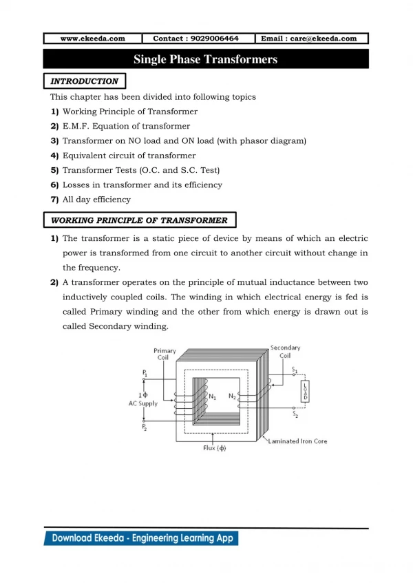
UPS Classification • Based on the topology the UPSes are classified to the three basic categories (IEC 62040-3): • Passive Standby (Off-line) • Line-interactive • Double Conversion (On-Line)
Basic UPS Topology - Off-line UPS Advantages: - Very low cost - High efficiency - Compact size • Disadvantages: • - Limited protection • - Not sinusoidal output • Uses battery during brownouts • Short drop-out during transition on battery MCU: - MC68HC908x
Basic UPS Topology - Line-Interactive UPS Advantages: - Medium cost - High efficiency - Better voltage conditioning Disadvantages: - Still limited protection - Short drop-out during transition on battery • MCU: • MC68HC908x • MC68HC908MRx
Basic UPS Topology- On-Line UPS • Advantages: • Excellent voltage conditioning • Full protection Disadvantages: - High cost - Low efficiency • Possible MCU: • HCS12E128 • DSP56F80x • DSP56F80xx • DSP56F83xx
Single Phase On-Line UPS Demo Using MC9S12E128 Single Phase On-Line UPS Demo Using MC9S12E128
Single Phase On-Line UPS Demo Using MC9S12E128 • Demo Features • Single Phase On-line Topology • 750 VA Output Power • 115/230 V Input Line • Controlled by MC9S12E128 • Single LED User Interface • 4 Status LEDs • 6 LEDs Bar Graph • 2 Buttons • Graphical User Interface on PC • Ready for GUI Display • Demo suitcase
Single Phase On-Line UPS Demo Using MC9S12E128 • Demo Concept • Four PCBs • UPS Power Stage • Input Filter • User Interface • MC9S12E128 Control Board • Demo case
Single Phase On-Line UPS Demo Using MC9S12E128 • Concept Schematic • Input Rectifier • Voltage Doubler • PFC • Average Current Mode PFC • Directly controlled by MCU • Output Inverter • True Sinusoidal Output • Directly controlled by MCU • Battery Charger • FlyBack DC-DC Converter • Controlled by TOP249Y (Power Integration, Inc.) • Max. Output Power: 60W • 3 – State Charging Algorithm (Bulk charge, Absorption, Float) controlled by MCU • DC-DC Step Up Converter • Push - Pull Converter • Directly Controlled by MCU • Max. Output Power: 560W Whole UPS controlled by one MC9S12E128 only
Single Phase On-Line UPS Demo Using MC9S12E128 • MC9S12E128 Features • 16-bit HCS12 CPU, 50 MHz core clock • 128K bytes of Flash EEPROM, 8K bytes of RAM • 3 x SCI, 1 x SPI, 1 x IIC • 3 x 4-channel 16-bit timer modules (TIM) • 6-channel 15-bit Pulse Modulator with Fault protection module (PMF) • 6-channel 8-bit Pulse Width Modulator (PWM) • 16-channel 10-bit analog-to-digital converter (ADC) • 2 x 1-channel 8-bit digital-to-analog converter (DAC) • Up to 16 pins available as Keypad Wake-Up inputs • 2 x additional external asynchronous interrupts • Up to 74 I/O port pins and 18 input only pins for 112 pin package • Up to 42 I/O port pins and 18 input only pins for 80 pin package
Single Phase On-Line UPS Demo Using MC9S12E128- HW Implementation • Battery Charger • Fly-Back Topology Converter • Dedicated circuit used (TOP249) • Output parameters • Output voltage: 29.4 or 27.4 V (set by MCU) • Output current: max. 1.8 A • Current limitation: 0 – 1.8 A (set by MCU) • Charge algorithm • 3 state (bulk charge, absorption, float) • MCU Interface • 2 analog inputs (battery voltage and battery current) • 1 analog output (PWM + filter, current limitation) • 1 digital output (output voltage 29.4 or 27.4 V)
Single Phase On-Line UPS Demo Using MC9S12E128- HW Implementation • Battery Charger Schematic
Single Phase On-Line UPS Demo Using MC9S12E128- HW Implementation • Battery Charging Algorithm • 3 Step Charging: Bulk, Absorption, Float
Single Phase On-Line UPS Demo Using MC9S12E128- HW Implementation • DC/DC Step Up Converter • Converts the battery voltage (24 V) to DC bus voltage (+/- 390V) • Push-Pull Topology • 50 kHz switching frequency • Fully controlled by MCU • Output parameters • Output Voltage: +/- 390 V • Output Current: 0.8 A • MCU interface • 2 analog inputs (+/- DC bus voltage) • 2 PWM outputs (PWM for transistors)
Single Phase On-Line UPS Demo Using MC9S12E128- HW Implementation • DC/DC Step Up Converter Schematic
Single Phase On-Line UPS Demo Using MC9S12E128- HW Implementation • Input Rectifier + Power Factor Correction (PFC) • Voltage doubler rectifier • PFC using bidirectional switch (one transistor only) • Control technique • Average Current Mode Control by MCU • 40 kHz switching frequency • Current control loop 50 ms • Voltage control loop 1 ms • Output parameters • Output power: 750 W • DC Bus voltage: +/- 390 V • MCU Interface • 4x analog input (2x DC bus voltage, 1x input current, 1x input voltage) • 1x PWM output (PFC transistor) • 1x Input Capture (Zero crossing)
Single Phase On-Line UPS Demo Using MC9S12E128- HW Implementation • Input Rectifier + PFC Controller Schematic
Single Phase On-Line UPS Demo Using MC9S12E128- HW Implementation • Output Inverter • Half bridge topology • 20 kHz switching frequency • Control technique • Fully controlled by MCU • PID controller + voltage feed forward + current feedback • 50 ms control loop • Output parameters • Output Voltage: 110 - 240 V • Output current: 3.3 A • MCU Interface • 4 analog input (2x DC bus voltage, 1x output current, 1x output voltage) • 2 PWM outputs (inverter transistors)
Single Phase On-Line UPS Demo Using MC9S12E128- HW Implementation • Output Inverter Schematic
Single Phase On-Line UPS Demo Using MC9S12E128- HW Implementation • MC9S12E128 Control Board • MC9S12E128 16-bit +5V Microcontroller operating at 25MHz • 8.00MHz crystal oscillator for MCU frequency generation • Background Debug Mode (BDM) interface connector • 2x Optically isolated RS-232 interface • Communication Header (SPI, SCI1, IIC) • PWM and Timer Header • Pulse Width Modulation, PWM, or Timer2, TIM2 Timer1, TIM1 • ADC and DAC Header • Analog-to-Digital Converter, ADC • Digital-to-Analog Converter, DAC Expansion Header for 16-bit Multiplexed Wide Bus • On-board power regulation from an external 12V DC supplied power input
Single Phase On-Line UPS Demo Using MC9S12E128- HW Implementation • MC9S12E128 Control Board - continue • Light Emitting Diode (LED) power indicator • One on-board real-time user debugging LEDs • Six on-board PWM monitoring LEDs • Six on-board PMF monitoring LEDs • Four on-board PMF Fault monitoring LEDs • UNI-3 Motor interface • Over-Voltage sensing • Over-Current sensing • Comparators for automatic current profiling • Encoder/Hall-Effect interface • Manual RESET push-button • General purpose and interrupt toggle switch • 2x General purpose and interrupt push-button
Single Phase On-Line UPS Demo Using MC9S12E128- HW Implementation • MC9S12E128 Control Board – Block Diagram
Single Phase On-Line UPS Demo Using MC9S12E128- SW Implementation • Software Structure • 5x periodical interrupts (2x 50 ms, 1x 1 ms, 1x 10 ms, 1x 50ms) • 3x event interrupts (PMF faults, LVI, SCI) • Background loop • Written in C language • Some critical algorithms written in assembler (sine wave generation, PID controllers, arithmetic functions)
Single Phase On-Line UPS Demo Using MC9S12E128- SW Implementation • Software Structure - continue
Single Phase On-Line UPS Demo Using MC9S12E128- SW Implementation • Software Structure - continue
Single Phase On-Line UPS Demo Using MC9S12E128- SW Implementation • Battery Charger Execution period: 50 ms
Single Phase On-Line UPS Demo Using MC9S12E128- SW Implementation • DC/DC Step Up Converter Execution period: 1 ms
Single Phase On-Line UPS Demo Using MC9S12E128- SW Implementation • Power Factor Correction Execution period: 1 ms Execution period: 50 ms
Single Phase On-Line UPS Demo Using MC9S12E128- SW Implementation • Output Inverter Execution period: 1 ms Execution period: 50 ms
Single Phase On-Line UPS Demo Using MC9S12E128- SW Implementation • Application State Machine
Single Phase On-Line UPS Demo Using MC9S12E128- Software Measurements • UPS Software Measurements • Code Length • FLASH memory: 10087 bytes • RAM memory: 3014 bytes (include stack 512 bytes) • MCU load: 77.5 % (without PCMaster serial communication) • PMF Reload 15.8 ms (period 50 ms) • ATD Complete 19.4 ms (period 50 ms) • TIM0 ch4 IC 7.8 ms (period 8.3 ms) • TIM0 ch5 OC 69 ms (period 1 ms) • TIM0 ch6 OC 43.4 ms (period 50 ms)
Single Phase On-Line UPS Demo Using MC9S12E128- Software Measurements • UPS Software Measurements - continues PMF Reload ATD Complete TIM0 ch5 OC TIM0 ch6 OC
Single Phase On-Line UPS Demo Using MC9S12E128- Performance Measurements • Load defined by IEC 62040-1 • Linear load (525 W) • R = 100 W • Non-linear load (750 VA) • R = 160 W • Rs = 2.8 W • C = 780 mF
Single Phase On-Line UPS Demo Using MC9S12E128- Performance Measurements • Overall efficiency – linear load
Single Phase On-Line UPS Demo Using MC9S12E128- Performance Measurements • Overall efficiency – non-linear load
Single Phase On-Line UPS Demo Using MC9S12E128- Performance Measurements • Output frequency - synchronized
Single Phase On-Line UPS Demo Using MC9S12E128- Performance Measurements • Output frequency – free running
Single Phase On-Line UPS Demo Using MC9S12E128- Performance Measurements • Output Voltage THD – without load
Single Phase On-Line UPS Demo Using MC9S12E128- Performance Measurements • Output Voltage THD – with linear load
Single Phase On-Line UPS Demo Using MC9S12E128- Performance Measurements • Output Voltage THD – with non-linear load
Single Phase On-Line UPS Demo Using MC9S12E128- Performance Measurements • Output Voltage THD – with non-linear load
Single Phase On-Line UPS Demo Using MC9S12E128- Performance Measurements • Output Voltage THD – with non-linear load
Single Phase On-Line UPS Demo Using MC9S12E128- Performance Measurements • Input Power Factor
Single Phase On-Line UPS Demo Using MC9S12E128- Performance Measurements • Output Power Factor (linear load)
Single Phase On-Line UPS Demo Using MC9S12E128- Performance Measurements • Load Step 20 % -> 100 %
Single Phase On-Line UPS Demo Using MC9S12E128- Performance Measurements • Load Step 20 % -> 100 %
Single Phase On-Line UPS Demo Using MC9S12E128- Performance Measurements • Load Step 100 % -> 20 %
Single Phase On-Line UPS Demo Using MC9S12E128- Performance Measurements • Load Step 100 % -> 20 %
Single Phase On-Line UPS Demo Using MC9S12E128- Performance Summary
Single Phase On-Line UPS Demo Using MC9S12E128- Developments tools • FreeMaster • Real time monitor • Read and write any variable in application • Display the variables in physical quantities • Scope • Recorder • Control page in HTML code