Single Phase Transformers
Ekeeda Provides Online Electrical and Electronics Engineering Degree Subjects Courses, Video Lectures for All Engineering Universities. Video Tutorials Covers Subjects of Mechanical Engineering Degree.

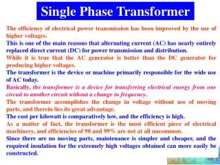
Single Phase Transformers
E N D
Presentation Transcript
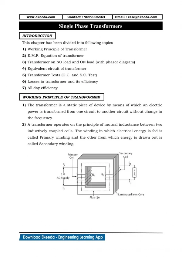
www.ekeeda.com Contact : 9029006464 Single Phase Transformers Email : care@ekeeda.com P INTRODUCTION This chapter has been divided into following topics 1)Working Principle of Transformer 2)E.M.F. Equation of transformer 3)Transformer on NO load and ON load (with phasor diagram) 4)Equivalent circuit of transformer 5)Transformer Tests (O.C. and S.C. Test) 6)Losses in transformer and its efficiency 7)All day efficiency WORKING PRINCIPLE OF TRANSFORMER 1)The transformer is a static piece of device by means of which an electric power is transformed from one circuit to another circuit without change in the frequency. 2)A transformer operates on the principle of mutual inductance between two inductively coupled coils. The winding in which electrical energy is fed is called Primary winding and the other from which energy is drawn out is called Secondary winding.
www.ekeeda.com Contact : 9029006464 Email : care@ekeeda.com 3)The primary winding has number of turns, while the secondary winding has N2 number of turns. The basic transformer and its symbol is shown in fig.(1) and (2) respectively. Fig.(1) Fig.(2) 4)When an alternating voltage V1 is applied to primary winding, an alternating current I1 flows in it producing alternating flux in the core. According to Faraday’s law of electromagnetic induction an e.m.f. is induced in the primary winding which is given by, where N1 is the number of turns in primary winding. The induced e.m.f. in the primary winding is nearly equal and opposite to the applied voltage V1. 5)Assuming leakage flux to be negligible, almost whole flux produced in primary winding links with the secondary winding. Hence e.m.f. e2 is induced in the secondary winding. where N1 is the number of turns in primary winding. If secondary circuit is closed through the load, a current I2 flows in the secondary winding. 6)Thus energy is transformed from primary winding to secondary winding through magnetic field.
www.ekeeda.com Contact : 9029006464 Email : care@ekeeda.com TYPES OF TRANSFORMERS According to their construction On the basis of construction, the transformers are classified in three types : 1) Shell Type Transformer, 2) Core Type Transformer 3) Berry Type Transformer 1.Shell Type Transformer : 1)For the construction of Shell type transformer a three limbed iron is used. Both primary and secondary windings are placed on central limb. 2)First primary winding is wound on the central limb with required number of turns. Then insulating paper is wrapped on this primary winding, then secondary winding is wound over this paper. 3)It has double magnetic circuit. The core encircles most of the part of winding. Generally it is preferred for very high voltage transformers. 4)As the windings are surrounded by core, the natural cooling does not exist. For removing any winding for maintenance, large number of laminations is required to be removed. 2.Core Type Transformer:-
www.ekeeda.com Contact : 9029006464 Email : care@ekeeda.com 1)For core type of transformer two limbed iron core is used. Primary and secondary winding turns are split in two parts and each part is arranged on both the limbs of core. 2)Initially first part of the primary windings is wound on one limb and remaining part of it is wound on other limb, then insulating paper is wrapped on each part of primary winding. Now secondary winding is wound on this paper in two parts, each part on one limb. 3)It has a single magnetic circuit. The winding encircles the core i.e. core is surrounded by the winding. Core is made up of large number of thin laminations. 4)As the windings are uniformly distributed over the two limbs the natural cooling is more effective. The coils can be easily removed by removing the laminations of the top yoke for maintenance. 3.Berry Type Transformer:- 1)This has distributed magnetic circuit. Its core construction is like spokes of a wheel. 2)These transformers are generally kept in tightly fitted sheet metal tanks. These tanks are filled with the special insulating oil. 3)The entire transformer assembly is immersed in the oil. The oil serves two functions: (a) keeps the windings cool by circulation and (b) provides additional insulation to transformer.
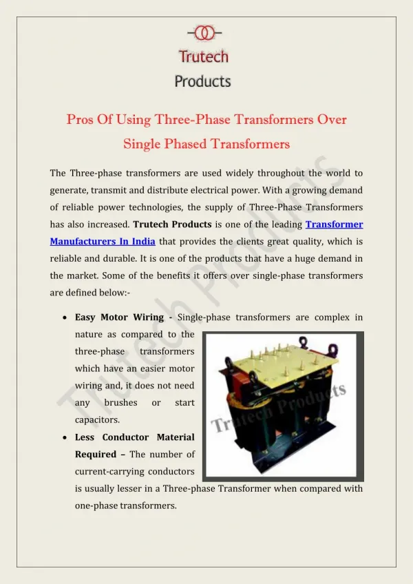
www.ekeeda.com Contact : 9029006464 Email : care@ekeeda.com According to their working On the basis of working, the transformers are classified in three types : 1) Step up Transformer 2) Step down Transformer 3) Isolation Transformer 1.Step up Transformer : 1)When the number of turns of secondary winding (N2) are greater than number of turns of primary windings (N1), then voltage available across secondary is greater than the applied across primary. 2)This kind of transformer is known as Step up Transformer where . 3)These type of transformers are generally used in generating power stations or in communication circuits as EHT Transformers. 2.Step down Transformer : 1)When the number of turns of secondary winding (N2) are less than number of turns of primary windings (N1), then voltage available across secondary is less than the applied across primary. 2)This kind of transformer is known as Step down Transformer (K >1) where 3)These type of transformers are generally used in distribution power stations and in electronics and communication circuits. 3.Isolation Transformer : 1)When the number of turns of secondary winding (N2) are equal to the number of turns of primary windings (N1), then voltage available across secondary is equal to voltage applied across primary.
www.ekeeda.com Contact : 9029006464 Email : care@ekeeda.com 2)This kind of transformer is known as Isolation Transformer (K = 1) where 3)These type of transformers are mainly used to isolate the electrical or electronic circuit under testing from the supply. EMF EQUATION OF TRANSFORMER 1)Let N1, N2 represents number of turns of primary and secondary windings respectively. e1 and e2 represents voltage induced across primary and secondary in volts. 2)As primary winding is excited by a sinusoidal alternating voltage, an alternating current flows in the winding producing a sinusoidally varying flux in the core. i.e. 3)As per Faraday’s law of electromagnetic induction an e.m.f. e1 is induced in the primary winding. 4)Therefore, maximum value of induced Hence RMS value of induced e.m.f. in primary winding is given by, ….(1) 5)Similarly RMS value of induced e.m.f. in secondary winding is given by, ….(2)
www.ekeeda.com Contact : 9029006464 Email : care@ekeeda.com 6)Also, Thus, e.m.f. per turns is same in primary and secondary winding and hence equal e.m.f. is induced in each turn of primary and secondary winding. ➢Transformation Ratio (K): 1)From eqn. (1) and (2) we have, …(3) …(4) Dividing (3) by (4) we get, …(5) The ratio , is known as Transformation ratio and is denoted by ‘K’. 2)If losses in a transformer are neglected the volt-ampere rating in the primary and secondary are equal. Thus, …(6) 3)Hence, current is transformed in the reverse ratio of the voltage. If a transformer steps up the voltage, it steps down the current and vice versa. For ideal transformer, ….(7) 4)From eqns (5), (6) and (7)
www.ekeeda.com Contact : 9029006464 Email : care@ekeeda.com ➢Rating of Transformer: 1)Rating of a transformer indicates the output power from it. But for a transformer, load is not fixed and its power factor goes on changing. Hence rating is expressed in terms of product of voltage and current called as VA rating. It is generally expressed in kVA. 2)kVA rating of Transformer = 3)We can calculate full load currents of primary and secondary windings from kVA rating of transformer. Full load primary current Full load primary current IDEAL TRANSFORMER 1.It is a transformer in which there are no losses i.e. 1)Copper losses in the windings are zero. (i.e. Resistance offered by the winding is zero.) 2)Iron losses in iron core of the transformer are zero. (i.e. core material has strong magnetic properties and provides zero reluctance and infinite permeability.) 3)No magnetic leakage. 2.When the primary of the ideal transformer is connected to an alternating voltage V1 with secondary open circuited, the primary draws very small amount of current (Iμ) from supply. This current is called as ‘magnetizing current’. This current is purely reactive current and lags the voltage V1 by 90˚.
www.ekeeda.com Contact : 9029006464 Email : care@ekeeda.com 3.This current (Iμ) set up the flux ( ) in iron core. The flux ( ) induces e.m.f.’s E1 and E2 in the primary and secondary windings. 4.These e.m.f. leads flux ( ) by . The induced voltage always opposes applied voltage . The magnitude of w.r.t. depends on transformation ratio (K). 5.The vector diagram for ideal transformer with i.e. K<1 is shown below : TRANSFORMER ON NO LOAD 1.Practically when transformer is connected to an alternating voltage V1, the primary will draw current (Io) from the supply. This current (Io) is called as ‘NO Load current’. 2.This current has two components : a)Magnetizing current (Iμ) : This component sets up the magnetic flux in the core. b)Working Current (Iω) : This current provides losses in iron core.
www.ekeeda.com Contact : 9029006464 Email : care@ekeeda.com 3.The NO load primary current Iois not 90˚ behind V1 but lags it by an angle . The phasor diagram for No load condition is shown below : 4.From phasor diagram, And is vector sum of and . Hence we have, No load power factor 5.The NO load i/p power is given by, 6.The NO load current is very small as compared to full load current . Hence copper loss is negligible and NO load input power is practically equal to iron loss or core loss in the transformer.
www.ekeeda.com Contact : 9029006464 Email : care@ekeeda.com TRANSFORMER ON LOAD Fig. (1) Fig. (2) Fig. (3) Fig. (4) 1.In fig. (1), on NO load condition the transformer primary draws a current Io from supply which has two components and .
www.ekeeda.com Contact : 9029006464 Email : care@ekeeda.com 2.In fig.(2), when a load with lagging power factor is connected across the secondary of transformer, secondary current (I2) starts flowing through the load. This secondary current sets up flux in iron core which opposes main flux . 3.Because of this net flux in the iron core decreases. Hence flux linking with primary coil reduces and induced e.m.f. E1 decreases. 4.In fig.(3), Due to reduction in induced voltage across primary (E1), potential difference is created. Thus primary will draw an extra amount of current (I1) to overcome load connected across secondary. This current is always out of phase with (I2). 5.This current ( ) generates flux ( ) which opposes flux ( ). This action cancels out flux ( ) and ( ). 6.In fig. (4), as flux ( ) and ( ) cancel out each other, the net flux in iron core becomes . Hence, magnetic flux in iron core of transformer remains same whether transformer is ON load or NO load condition. 7.As flux in iron core of transformer remains constant, iron losses in transformer remains constant. Hence iron losses are called constant losses. 8.Now net current in primary is I1 which is vector addition of and i.e. 9.The complete phasor diagram of transformer ON load is shown below. PRACTICAL TRANSFORMER [TRANSFORMER WITH LEAKAGE IMPEDANCE]
www.ekeeda.com Contact : 9029006464 Email : care@ekeeda.com 1.Let R1, R2 Resistance of primary and secondary. Reactance of primary and secondary. Impedance of primary and secondary. Thus, and 2.Applying KVL to primary side, (Because E1 is opposite to V1.) (Where ) 3.Applying KVL to Secondary side, Steps to draw phasor diagram (for lagging power factor) 1.Consider flux φ as reference vector. 2.Draw vector E1 laggingφ by 90˚. 3.Draw vector E2 in phase with E1. (Length of E2 depends on turns ratio) 4.Extend E1 in opposite direction and mark it as –E1. 5.Draw vector Iμ alongφ and Iω along (-E1). Then draw their resultant Io making an angleφ0 with (-E1). 6.Draw vector I2 lagging E2.
www.ekeeda.com Contact : 9029006464 Email : care@ekeeda.com 7.Draw I2R2 in phase with I2 and I2X2 perpendicular to I2R2. Draw their resultant as I2Z2. 8.Extend I2Z2 in negative direction and draw resultant of -I2Z2 and E2. Label this resultant as V2 and angle between V2 and I2 asφ2. 9.Extend I2 in opposite direction and get the vector I2’ such that I2’ =K I2. 10.Find the resultant of I2’ and I0. Label this resultant as I1. i.e. net primary current. 11.Draw vectors I1R1 in phase with I1 and I1X1 perpendicular to I1R1. Draw their resultant as I1Z1. 12.Get the resultant of I1Z1 and (-E1). Label this resultant as V1 and angle between V1 and I1 asφ1. PHASOR DIAGRAM FOR LAGGING POWER FACTOR PHASOR DIAGRAM FOR LEADING POWER FACTOR
www.ekeeda.com Contact : 9029006464 Email : care@ekeeda.com PHASOR DIAGRAM FOR UNITY POWER FACTOR EQUIVALENT CIRCUIT OF TRANSFORMER
www.ekeeda.com Contact : 9029006464 Email : care@ekeeda.com NO Load Condition 1)When transformer is on NO load condition it draws a current Io which has got two components. (a) Iμ = Io sinφo which produces flux and (b) Iω = Io cosφo which provides iron loss. 2)Consider Two imaginary components Ro and Xo. The current Iω flows through Ro to provide iron loss and current Iμ flows through Xo to produce fluxφ. 3)The equivalent circuit of transformer on NO load condition is shown below: 4)From circuit diagram, and ON Load Condition 1.When load ZL is connected across secondary of transformer, current I2 flows through secondary winding and causes voltage drop across R2 and X2 of the secondary winding. Total current drawn by primary of transformer under load is I1. 2.The equivalent circuit of transformer ON load is shown below : 3.But, this circuit is complicated for analysis. This can be simplified by transforming secondary parameters to primary or vice-versa.
www.ekeeda.com Contact : 9029006464 Email : care@ekeeda.com a)Equivalent Circuit of transformer referred by primary:- 1)When secondary parameters are transferred to primary side then equivalent circuit so obtained is known as Equivalent circuit of transformer referred to Primary. 2)This equivalent circuit is shown below: 3)If , then secondary parameters referred to primary are, b)Equivalent Circuit of transformer referred to secondary : 1)When primary parameters are transferred to secondary side then equivalent circuit so obtained is known as Equivalent circuit of transformer referred to Secondary. 2)This equivalent circuit is shown below : 3)If then primary parameters referred to secondary are, APPROXIMATE EQUIVALENT CIRCUIT OF TRANSFORMER
www.ekeeda.com Contact : 9029006464 Email : care@ekeeda.com 1)The approximate equivalent circuit of transformer can be obtained by shifting the parallel combination of imaginary components Ro and Xo to the left of the circuit. 2)By shifting this parallel branch we are neglecting the drops across R1 and X1 due to Io as |Io| is very small. Approximate Circuit referred to Primary This circuit can be further simplified as shown below : where, R1e Equivalent resistance of transformer referred to primary X1e Equivalent reactance of transformer referred to primary Z1e Equivalent impedance of transformer referred to primary ,
www.ekeeda.com Contact : 9029006464 Email : care@ekeeda.com APPROXIMATE CIRCUIT REFERRED TO SECONDARY This circuit can be further simplified as shown below: where, R2e Equivalent resistance of transformer referred to secondary X2e Equivalent reactance of transformer referred to secondary Z2e Equivalent impedance of transformer referred to secondary , Voltage Regulation of Transformer 1)When a transformer is loaded, the secondary terminal voltage decreases due to drop across secondary winding resistance and leakage reactance. 2)This change in secondary terminal voltage from NO load to full load condition expressed as fraction of the NO load secondary voltage is called as Regulation of Transformer.
www.ekeeda.com Contact : 9029006464 Email : care@ekeeda.com 3)The secondary terminal voltage does not depend only on load current but also on the power factor of the load. Consider secondary circuit as shown below: 4)Applying KVL to secondary circuit we get, Thus, phasor diagrams for different power factors are shown below: a)Lagging p.f. For lagging p.f. Regulation is positive for lagging p.f. b)Leading p.f. For leading p.f. Regulation is negative for leading p.f. c)Unity p.f. For unity p.f. Regulation is positive for unity p.f. 5)In general the expression for Voltage regulation is,
www.ekeeda.com Contact : 9029006464 Email : care@ekeeda.com LOSSES IN TRANSFORMER AND EFFICIENCY Losses in Transformer a)Copper Losses:- 1)This loss is due to the resistance of primary and secondary windings. 2)It depends on load current and is proportional to square of the load current. b)Iron Losses (or Core Losses):- 1)This loss includes hysteresis and eddy current loss. Hysteresis loss occurs due to setting of alternating flux in the core. Eddy current loss occurs due to setting of eddy currents in the core which is due to induced e.m.f. in the core. 2)These losses are also known as constant losses. Hysteresis and eddy current loss is given by, and Efficiency of Transformer 1)We know that efficiency is the ratio of output power to input power. 2)But for any machine, Power Input = Power Output + Losses
www.ekeeda.com Contact : 9029006464 Email : care@ekeeda.com Condition for Maximum Efficiency of Transformer 1)Considering secondary side of transformer, Differentiating both the sides w.r.t. , But for maximum efficiency, Similarly on primary side, Thus, Efficiency of Transformer is maximum when, Copper Loss = Iron Loss All Day Efficiency of Transformer 1)The transformers used for distribution are energized for 24 hours of the day. Thus, constant losses occur in the transformer for the whole day. 2)These transformers normally operate on different loads during 24 hours a day. Because of this copper losses are different during different periods of day. 3)Hence, efficiency of such transformers should be measured on the energy basis.
www.ekeeda.com Contact : 9029006464 Email : care@ekeeda.com TRANSFORMER TESTS 1.The performance of transformer can be studied from its equivalent circuit. The parameters of transformer can be calculated by conducting two tests (a) Open Circuit Test and (b) Short Circuit Test. 2.These tests are economical and convenient, because we can find transformer parameters without actually loading it. (a)Open Circuit (O.C.) Test:- 1)The purpose of this test is to determine (1) Iron loss Wi (3) Magnetizing reactance Xo 2)The above fig. shows the circuit diagram for conducting O.C. test on the transformer. In this test one winding is left open and other winding is connected to a supply. 3)Ammeter, Voltmeter and wattmeter are connected on the side where supply is connected. 4)Ammeter indicates NO load current drawn by the transformer. As the NO load current is usually 3 to 5% of full load current, copper losses will be negligible and wattmeter will indicate iron loss. 5)If meters are connected on primary side, (2) Magnetizing resistance Ro and
www.ekeeda.com Contact : 9029006464 Email : care@ekeeda.com Wattmeter reading = Wi Voltmeter reading = V1 Ammeter reading = Io Also, And , (b)Short Circuit (S.C.) Test:- 1)The purpose of this test is to determine (1) full load copper loss, (2) equivalent resistance R1e or R2e and (3) equivalent reactance X1e or X2e 2)The fig. shows the circuit diagram for conducting S.C. test on transformer. In this test one winding is short circuited, while a low voltage is applied to the other winding. 3)The voltage is slowly increased until full load current flows in this winding. 4)Normally, the applied voltage is 5 to 10% of rated voltage of this winding. Hence flux produced in the core will be small and so the iron losses are very small. Thus wattmeter indicates full load copper loss. 5)If meter is connected on primary side, Wattmeter reading = Wsc
www.ekeeda.com Contact : 9029006464 Email : care@ekeeda.com Voltmeter reading = Vsc Ammeter reading = Isc and