Download
1 / 4
40 likes | 83 Views
This paper is designed to build movable bridge for passable both land and marine transportation and upgrade transportation system for people. In this paper, Arduino Uno, ultrasonic sensor, servo motor, 2channel relay and gear motor are used as mainly devices. Ultrasonic sensor is running by emitting waves until the ship is coming. As soon as the ship is passing, the sensor is sent data to arduino. And then, arduino microcontroller control the traffic light on the land by changing green led to red led. In this condition, the servo motor start to run and gate on the land is closed. After gate is closed, the gear motor start to run and lift the bridge to cross the ship. When the ship is passed, the bridge down to normal state and red led change to green led. When the led is green, the servo motor start to run and gate is open. At this time, the cars can pass safety. Nwe Nwe Oo | May Thwe Oo | Hla Yamin "Design and Construction of Movable Bridge using Arduino" Published in International Journal of Trend in Scientific Research and Development (ijtsrd), ISSN: 2456-6470, Volume-3 | Issue-5 , August 2019, URL: https://www.ijtsrd.com/papers/ijtsrd25285.pdf Paper URL: https://www.ijtsrd.com/engineering/electronics-and-communication-engineering/25285/design-and-construction-of-movable-bridge-using-arduino/nwe-nwe-oo<br>

E N D
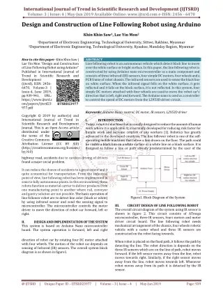
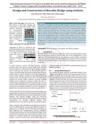
International Journal of Trend in Scientific Research and Development (IJTSRD) Volume 3 Issue 5, August 2019 Available Online: www.ijtsrd.com e-ISSN: 2456 – 6470 Design and Construction of Movable Bridge using Arduino Nwe Nwe Oo1, May Thwe Oo2, Hla Yamin1 1Lecturer, 2Professor 1,2Department of Electronic Engineering, Technological University (Magway), Myanmar How to cite this paper: Nwe Nwe Oo | May Thweoo | Hla Yamin "Design and Construction of Movable Bridge using Arduino" Published in International Journal of Trend in Scientific Research and Development (ijtsrd), ISSN: 2456- 6470, Volume-3 | Issue-5, August 2019, https://doi.org/10.31142/ijtsrd25285 Copyright © 2019 by author(s) and International Journal of Trend in Scientific Research and Development Journal. This is an Open Access article distributed under the terms of the Creative Commons Attribution License (CC (http://creativecommons.org/licenses/by /4.0) In most instances, marine craft have priority, and the movable span must open to marine traffic upon demand. This precedence is reflected in the terms closed and open, used to describe the position of the movable spans. A “closed” movable bridge has closed the waterway to marine traffic, while an “open” bridge has open the waterway to marine traffic. Highway bridges are typically designed to remain in the closed position and only to be open when required by marine traffic. However, movable railroad bridges can be designed to remain in either the open or closed position, depending on how frequently they are used by train traffic. The difference is important as different wind and seismic load design conditions are used to design for a brigde that is usually open and one that is usually closed. The first specification for the design of movable bridges was published by the American Railway Engineering Association (AREA). This specification was used to design both movable highway and railroad bridges, when the American Association of State Highway Officials published its standard specifications for movable Highway Bridges. Both specifications are very similar, but have remained separate. Today, movable railroad bridges are designed in accordance with the AREA Manual, and movable highway bridges are designed in accordance with the American Association of State Highway and Transportation Officials (AASHTO) Standard Specifications for Movable Highway Bridges. These specifications primarily cover the mechanical and electrical aspects of a movable bridge; the structural design of the bridge is covered in other parts of the AREA Manual for ABSTRACT This paper is designed to build movable bridge for passable both land and marine transportation and upgrade transportation system for people. In this paper, Arduino Uno, ultrasonic sensor, servo motor, 2channel relay and gear motor are used as mainly devices. Ultrasonic sensor is running by emitting waves until the ship is coming. As soon as the ship is passing, the sensor is sent data to arduino. And then, arduino microcontroller control the traffic light on the land by changing green led to red led. In this condition, the servo motor start to run and gate on the land is closed. After gate is closed, the gear motor start to run and lift the bridge to cross the ship. When the ship is passed, the bridge down to normal state and red led change to green led. When the led is green, the servo motor start to run and gate is open. At this time, the cars can pass safety. KEYWORDS: Ultrasonic Sensor, Servo Motor, Gear Motor, Arduino I. Introduction Movable bridges have been an integral part of the U.S transportation system, their development being in concert with that of the development of the railroads and the development of our highway system. While sometimes referred to as draw bridges, movable bridges have proved to be an economical solution to the problem of how to carry a rail line or highway across an active waterway. railroad bridges or the AASHTO Standard Specifications for Highway Bridges. II. System Block Diagram Fig.1 shows the block diagram of Movable Bridge. Power supply is provided to arduino and 2channel relay. Sensor is used to sense the objects (eg ship). When the sensor sense the ship is passing, the green LED switch on-off delay 5s and change to yellow led then, the yellow LED is set 5s delay later, change yellow led to red led. When led is red, the servo motor start to run and gate is closed. Hydraulic is lift up the bridge with 3 minutes delay after gate is closed. Hydraulic is fall down with 1 minutes delay after lift up 3 minutes. The bridge is down to normal state, change red LED to the green LED. The green LED is turn on and the boom gate open. IJTSRD25285 pp.386-389, BY 4.0) Fig.1: Block Diagram of Movable Bridge @ IJTSRD | Unique Paper ID – IJTSRD25285 | Volume – 3 | Issue – 5 | July - August 2019 Page 386
International Journal of Trend in Scientific Research and Development (IJTSRD) @ www.ijtsrd.com eISSN: 2456-6470 III. 1.Ultrasonic Sensor System components its motion and final position. The input to its control is a signal (either analogue or digital) representing the position commanded for the output shaft. 4.2ChannelModule Relay A relay is defined as an electrically operated switch; their main use is controlling circuits by a low-power signal or when several circuits must be controlled by one signal. The first relay was used in long distance telegraph circuits as amplifiers, basically they repeated the signal they received from one circuit, and transmitted it into a different one, they were also used in early computers to perform logical operations. The sonic waves emitted by the transducer are reflected by an object and received back in the transducer. After having emitted the sound waves, the ultrasonic sensor will switch to receive mode. The time elapsed between emitting and receiving is proportional to the distance of the object from the sensor. Ultrasonic sensor are devices that use electrical– mechanical energy transformation to measure distance from the sensor to the target object. The HC-SR04 ultrasonic sensor uses sonar to determine distance to an object like bats or dolphins do. It provides 2cm to 400cm of non-contact measurement functionality with a ranging accuracy that can reach up to 3mm. Each HC-SR04 module includes an ultrasonic transmitter, a receiver and a control circuit. There are only four pins that you need to worry about on the HC- SR04: VCC (power), Trig (Trigger), Echo (Receiver) and GND (Ground). 2.Gear Motor A gear motor is a specific type of electrical motor that is designed to produce high torque while maintaining a low horsepower, or low speed, motor output. A gear motor is a specific type of electrical motor that is designed to produce high torque while maintaining a low horsepower, or low speed, motor output. Gear motors can be found in many different applications, and are probably used in many devices in your home 5.Arduino UNO Arduino is an open source computer hardware and software company, project, and user community that designs and manufactures single-board microcontroller kits for building digital devices and interactive objects that can sense and control objects in the physical and digital world. Arduino Uno is a microcontroller board. It has 14 digital input/output pins (of which 6 can be used as PWN outputs), 6 analog inputs, a 16MHz quartz crystal, a USB connection, a power jack, an ICP header and a reset button. It contains everything needed to support the microcontroller; simply connect it to a computer with a USB cable or power it with a AC to DC adapter or battery to get started. microcontrollers and 3.ServoMotor A servomotor is a rotary actuator or liner actuator that allows for precise control of angular or liner position, velocity and acceleration. It consists of a suitable motor coupled to a sensor for position feedback. It also requires a relatively sophisticated controller, often a dedicated module designed specifically for use with servomotors. Servomotors are not a specific class of motor although the term servomotor is often used to refer to a motor suitable for use in a closed-loop control system that used position feedback to control its motion and final position feedback to control @ IJTSRD | Unique Paper ID – IJTSRD25285 | Volume – 3 | Issue – 5 | July - August 2019 Page 387
International Journal of Trend in Scientific Research and Development (IJTSRD) @ www.ijtsrd.com eISSN: 2456-6470 IV. Circuit Design of Movable Bridge Start Port Initialization Read signal From sensor NO If sensor value = 1? Fig.2: Overall Circuit Diagram of Movable Bridge AC 220V change to AC 12V by using step down transformer. Then, use two diode and 1000uF 16V capacitor to produce 12V pure DC output. And then, 12V DC connect with LN 7808 voltage regulator and 1000uF 16V capacitor to get 8V pure DC output. DC 12V use for 2channel relay to run geared motor and DC 24V use for controller. Ultrasonic sensor has four pins. There are Vcc, trigger, echox ground. The sensor connect with arduino, vcc connect with 5v dc supply. If the ship is passing, the sensor is informing to arduino. Arduino is running program according to step by step procedure. The green LED connect with pin5. The yellow led connect with pin no6. The red LED connect with pin no7. The green LED switch on-off delay 5s and change to yellow LED then, the yellow LED is set 3s delay later, change yellow LED to red LED. When LED is red, the servo motor run. Servo motor connect with pin no 10. At normal state, servo motor is opening gate by 90 degree position when a ship is coming, the gate start closing 90 degree to 0 degree due to the program.2 channel relay connect with pin no 3 and pin no4. In normal state, center is connect with normally close. When the pin no 3 is high, center connect to normally open and start rotate gear motor. Gear motor is to run hydraulic for lift up of the brddge when the ship is coming. Gear motor is running reverse direction to lift the bridge. After the ship is passing, pin no 4 is low and gear motor is running forward direction to down the bridge at normal state. V. Overall System Flowchart Firstly, sensor is sensing ship by emitting wave signal. When the sensor sense the ship, the green LED switch on and switch off delay 5s and green LED change to yellow led. Then, the yellow LED change to red LED delay with 0.5s. When led is red, the servo motor run and gate is closed. After gate is closed, hydraulic is lifting up the bridge delay with 16s. Hydraulic is down the bridge delay with 6.5s.When the bridge is down to normal state, red LED change to green LED. Then, the green led is turn on and the gate is open. At this time, the cars can pass the bridge. YES Change green LED to yellow LED ( Delay 5s ) Change yellow LED to red LED ( Delay 0.5s ) Red LED and Servo Motor run ( Gate close ) Hydraulic Up ( Delay 16s ) Hydraulic down ( Delay 6.5s ) Change red LED to green LED ( Delay 1s ) Green LED and Servo motor run ( Gate open ) End Fig.3: System Flow Chart VI. Results Fig.4: Result for the Condition of Green LED and Gate Open @ IJTSRD | Unique Paper ID – IJTSRD25285 | Volume – 3 | Issue – 5 | July - August 2019 Page 388
International Journal of Trend in Scientific Research and Development (IJTSRD) @ www.ijtsrd.com eISSN: 2456-6470 town. In this paper, arduino is used to control the overall system process design The bridge system use arduino, servo motor, Gear motor, LED, ultrasonic sensor, 2channel relay, resistor and other accessories. C++ programming language is used for Arduino that control other components. Gear motor is use to lift up and down the bridge. Servomotor is used for boom gate. Ultrasonic sensor is sensing for obstacles and the sensor is informing to arduino. LEDs are used for traffic light for boom gate. 2channel relay use forward and reverse rotation for gear motor. VIII. Further Extension Nowadays, Land and marine transportations are used mainly. So, movable bridges are need to pass both car and ship transportation. Furthermore, the movable bridge can be advanced by using other microcontroller and sensor such as PIC microcontroller, IR sensor, Laser Light sensor and so on. If this system will be used IR sensor, e.g. when the ship is coming, the sensor can sense level of ship and report to microcontroller how to process. IX. References [1]Lloyd, 12 October 2011, “Transporter Bridge Left Boats in Its Wake”. Fig.5: Testing Result for the Condition of Yellow LED [2]Encyclopadia Britannica, 8 October 2012, “Covered Bridge”. [3]WoodWortman, 2006, “The Portland Bridge Book”, 3rd Edition. [4]Lu, Malvern, Jenkins, October 1982, “Balancing of Trunnion Type Bascule Bridges”.. [5]Truscott, Alan; Truscott, 2002, “The New York Times Bridge Book”. [6]Frank E, SadowskiJr, 24 July 2013, “The Fairport Lift Bridge”. Fig.6: Result for the Condition of Red LED and Gate Close VII. Discussion This paper is discussed about Movable bridge that can be used in marine and land which is too many transportation and used in where difficult to dig canal for shipping way. It can also use in narrow river and low level ground in the [7]Kutz, Myer, 2011, “Handbook of Transportation Engineering”. [8]Francis, Henry, 1994, “The Official Encyclopedia of Bridge”. @ IJTSRD | Unique Paper ID – IJTSRD25285 | Volume – 3 | Issue – 5 | July - August 2019 Page 389