Download
1 / 3
60 likes | 143 Views
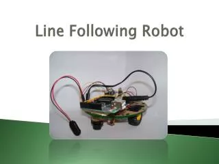
Line following robot is an autonomous vehicle which detect black line to move over the white surface or bright surface. In this paper, the line following robot is constructed by using Arduino nano microcontroller as a main component and consists of three infrared IR sensors, four simple DC motors, four wheels and a PCB frame of robot chassis. The infrared sensors are used to sense the black line on white surface. When the infrared signal falls on the white surface, it gets reflected and it falls on the black surface, it is not reflected. In this system, four simple DC motors attached with four wheels are used to move the robot cars direction that is left, right and forward. The Arduino nano is used as a controller to control the speed of DC motors from the L2953D driver circuit. Khin Khin Saw | Lae Yin Mon "Design and Construction of Line Following Robot using Arduino" Published in International Journal of Trend in Scientific Research and Development (ijtsrd), ISSN: 2456-6470, Volume-3 | Issue-4 , June 2019, URL: https://www.ijtsrd.com/papers/ijtsrd23977.pdf Paper URL: https://www.ijtsrd.com/engineering/electronics-and-communication-engineering/23977/design-and-construction-of-line-following-robot-using-arduino/khin-khin-saw<br>

E N D
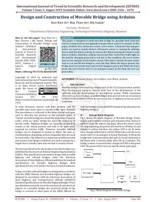
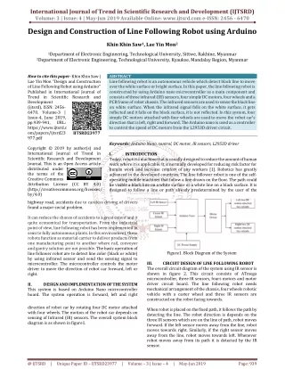
International Journal of Trend in Scientific Research and Development (IJTSRD) Volume: 3 | Issue: 4 | May-Jun 2019 Available Online: www.ijtsrd.com e-ISSN: 2456 - 6470 Design and Construction of Line Following Robot using Arduino Khin Khin Saw1, Lae Yin Mon2 1Department of Electronic Engineering, Technological University, Sittwe,Rakhine, Myanmar 2Department of Electronic Engineering, Technological University, Kyaukse, Mandalay Region, Myanmar How to cite this paper: Khin Khin Saw | Lae Yin Mon "Design and Construction of Line Following Robot using Arduino" Published in International Journal of Trend in Scientific Research and Development (ijtsrd), ISSN: 2456- 6470, Volume-3 | Issue-4, June 2019, pp.939-941, URL: https://www.ijtsrd.c om/papers/ijtsrd23 977.pdf Copyright © 2019 by author(s) and International Journal of Trend in Scientific Research and Development Journal. This is an Open Access article distributed under the terms of the Creative Commons Attribution License (CC BY 4.0) (http://creativecommons.org/licenses/ by/4.0) highway road, accidents due to careless driving of drivers found a major social problem. It can reduce the chance of accidents to a great extent and it quite economical for transportation. From the industrial point of view, line following robot has been implemented in semi to fully autonomous plants. In this environment, these robots function as material carrier to deliver products from one manufacturing point to another where rail, conveyor and gantry solution are not possible. The basic operation of line follower robot are to detect line color (black or white) by using infrared sensor and send the sensing signal to microcontroller. The microcontroller controls the motor driver to move the direction of robot car forward, left or right. II. DESIGN AND IMPLEMENTATION OF THE SYSTEM This system is based on Arduino Nano microcontroller board. The system operation is forward, left and right direction of robot car by rotating four DC motor attached with four wheels. The motion of the robot car depends on sensing of Infrared (IR) sensors. The overall system block diagram is as shown in figure1. ABSTRACT Line following robot is an autonomous vehicle which detect black line to move over the white surface or bright surface. In this paper, the line following robot is constructed by using Arduino nano microcontroller as a main component and consists of three infrared (IR) sensors, four simple DC motors, four wheels and a PCB frame of robot chassis. The infrared sensors are used to sense the black line on white surface. When the infrared signal falls on the white surface, it gets reflected and it falls on the black surface, it is not reflected. In this system, four simple DC motors attached with four wheels are used to move the robot car's direction that is left, right and forward. The Arduino nano is used as a controller to control the speed of DC motors from the L2953D driver circuit. Keywords: Arduino Nano, control, DC motor, IR sensors, L2953D driver I. INTRODUCTION Today, robot is a machine that is usually designed to reduce the amount of human work where it is applicable. It is normally developed for reducing risk factor for human work and increase comfort of any workers [1]. Robotics has greatly advanced in the developed countries. The line follower robot is one of the self- operating mobile machines that follow a line drawn on the floor. The path could be visible a black line on a white surface or a white line on a black surface. It is designed to follow a line or path already predetermined by the user of the IJTSRD23977 Figure1. Block Diagram of the System III. The overall circuit diagram of the system using IR sensor is shown in figure 2. This circuit consists of ATmega microcontroller, three IR sensors, fours motors and motor driver circuit board. The line following robot needs mechanical arrangement of the chassis, four wheels robotic vehicle with a caster wheel and three IR sensors are constructed on the robot facing towards. When robot is placed on the fixed path, it follows the path by detecting the line. The robot direction is depends on the three IR sensors which are on the line of path, robot moves forward. If the left sensor moves away from the line, robot moves towards right. Similarly, if the right sensor moves away from the line, robot moves towards left. Whenever robot moves away from its path it is detected by the IR sensor. CIRCUIT DESIGN OF LINE FOLLOWING ROBOT @ IJTSRD | Unique Paper ID – IJTSRD23977 | Volume – 3 | Issue – 4 | May-Jun 2019 Page: 939
International Journal of Trend in Scientific Research and Development (IJTSRD) @ www.ijtsrd.com eISSN: 2456-6470 When IR sensors transmit the signal and it reflect the surface area and receive from surface area as the receiver. The electrical signals from Arduino Nano flow into the data pin connected with it. ?Enable A (ENA) input is connected arduino digital pin 3 ?Enable B (ENB) input is connected arduino digital pin 5 ?Input pin 1 is connected arduino digital pin 11 ?Input pin 2 is connected arduino digital pin 10 ?Input pin 3 is connected arduino digital pin 9 ?Input pin 4 is connected arduino digital pin 6 ?Output pin 1 is arduino digital pin 2 connect with left IR sensor. ?Output pin 2 is ardunio digital pin 4 connect with center IR sensor. ?Output pin 3 is ardunio digital pin 7 connect with right sensor To work as it program, motor driver circuit board as a signal and is able to adjust and work continuously motor as the signal flow constantly. As line following robot in this project is contract to pass on the black line on a white surface or bright surface area. the wheels is changed as this data is achieved. The right wheel is held and the left wheel is made to move freely until the response from the center sensor become high. Then the same process repeats again. In the third step, when a left curve is found on the line response of the right sensor will be change from low to high as the sensor. Then the control of the wheel changes by holding the right wheel and allowing the left wheel to move freely until the center sensor changes it from low to high. The same processes continue for all the turns and the robot moves continuously until the supply is removing. If all the three sensors will be on white surface area then they all will below and as no line is detected, robot move in a circular motion until line is found. If no line is detected, circle unit is found. Table 1 shows direction and movement of robot car. Table1. Direction and Movement of Robot Car Robot Movement Left Motor Straight Left Right V. WORKING PRINCIPLE OF LINE FOLLOWING ROBOT Line following robot senses black line by using Infrared sensor and then sends the signals to Arduino. The three IR sensors are used for path detection purpose. These sensors attached at the front end of the robot. When IR sensors transmit the signal and it reflect the surface area and receive from surface area as the receiver. The electrical signals from Arduino Nano flow into the data pin connected with it. To work as its program, the signal flow into the motor driver card as a signal and is able to adjust and work continuously motor driver as the signal flow frequently. As line following robot is contracting to pass on the black line, it pass as its line. If line is centered in front of robot, line following robot goes forward. When the center sensor is high and the remaining sensor is low the center sensor is will always be on the line and as line is black in color. Right Motor 1 1 0 1 0 1 Figure2. Circuit Diagram of Speed Detection System IV. The overall flow chart of the system is shown in figure 3. In the first step, when center sensor senses black line, robot car goes forward direction. Center sensor response is high and the remaining two sensors response is low. According to arrangement the center sensor will be on the line and as the line is black in color it will not reflect the emitted radiation back and the response of the sensor will low and the response of the remaining two sensors will be low as they will be on the bright surface. OVERALL FLOW CHART OF THE SYSTEM Figure4. Forward direction If line is left of center, beside of the robot, it turns left. When the left sensor is high and the remaining sensor is low the center sensor is will always be on the line and as line is black in color. Figure3. Overall Flow Chart of the System In the second step, when a right curve is found on the line response will be change the response of the left sensor high and the reaming sensors response will be low. The control of @ IJTSRD | Unique Paper ID – IJTSRD23977 | Volume – 3 | Issue – 4 | May-Jun 2019 Page: 940
International Journal of Trend in Scientific Research and Development (IJTSRD) @ www.ijtsrd.com eISSN: 2456-6470 Figure8. Left Direction of Line Following Robot Figure5. Left direction If line is right of center, the robot turns right. When the right sensor is high, the remaining sensor is low and the center sensor is will always be on the line and as line is black in color. If no line is detected, circle unit is found. Figure9. Right Direction of Line Following Robot Figure6. Right direction VI. VI. TEST AND RESULT OF LINE FOLLOWING ROBOT In this section, testing results of the system are shown that are the direction of line following robot, forward, left and right. According to the testing of line following robot, the speed of the motors (pwm) is able to change the limitation between 0 and 255. Figure 7 shows hardware implementation of line following robot. Figure10. Forward Direction of Line Following Robot The motor speed (pwm) is 145 and 150. Line following robot car move according to the working principle and the system operation is repeated by sensing signal of three IR sensors. VII. CONCLUSION Design and construction of line following robot was designed in this paper. This design is based on Arduino microcontroller. The robot car moves left, right and forward direction on the black line of white surface by using four simple DC motors attached with four wheels. The speed of the motors is controlled by L293D driver circuit. The directions of the robot car are controlled by using sensing signal of IR sensors from Arduino nano microcontroller. The colour is sensed by using three IR sensors. If the sensing colour is white, robot car moves and if the sensing colour is black, robot car does not move. REFERENCES [1]https://www.electronicshub.org, arduino-car-speed- detector. Figure7. Implementation of Line Following robot The following results are forward, left and right direction of line follower robot. Figure 8 shows the robot car turn to right. Figure 9 shows the robot car turn to right direction. Figure 10 shows the robot car turn to forward direction. [2]http://www.ardunio.cc/en/Main/ardunioBoardUno [3]https://www.i-robotics blogspot.com [4]https://www.circuit digest.com [5]www.swyhome.com @ IJTSRD | Unique Paper ID – IJTSRD23977 | Volume – 3 | Issue – 4 | May-Jun 2019 Page: 941