Download
1 / 4
40 likes | 56 Views
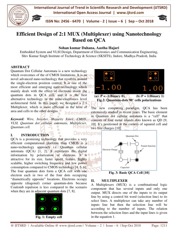
Quantum Dot Cellular Automata is a new technology which overcomes of the of CMOS limitations. It is an novel advanced nano technology that revolves around the single electron position control. It is one of the most efficient and emerging nano technology which mainly deals with the effect of electrons inside the quantum dots in QCA cell, and it is the best alternative technology in the nano electronics level architectural field. In this paper, we designed a 2 1 Multiplexer, which is more efficient in the term of area and cells to the other designs. Sohan kumar Dahana | Aastha Hajari "Efficient Design of 2:1 MUX (Multiplexer) using Nanotechnology Based on QCA" Published in International Journal of Trend in Scientific Research and Development (ijtsrd), ISSN: 2456-6470, Volume-2 | Issue-6 , October 2018, URL: https://www.ijtsrd.com/papers/ijtsrd18858.pdf Paper URL: http://www.ijtsrd.com/engineering/electronics-and-communication-engineering/18858/efficient-design-of-21-mux-multiplexer-using-nanotechnology-based-on-qca/sohan-kumar-dahana<br>

E N D
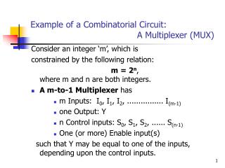
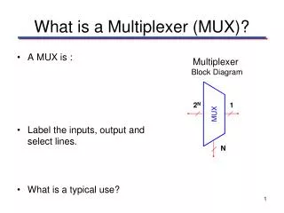
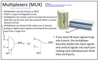
International Journal of Trend in International Open Access Journal International Open Access Journal | www.ijtsrd.com International Journal of Trend in Scientific Research and Development (IJTSRD) Research and Development (IJTSRD) www.ijtsrd.com ISSN No: 2456 ISSN No: 2456 - 6470 | Volume - 2 | Issue – 6 | Sep 6 | Sep – Oct 2018 Efficient Design of 2:1 MUX (Multiplexer f 2:1 MUX (Multiplexer) using Nanotechnology Based on QCA ) using Nanotechnology Sohan kumar Dahana Sohan kumar Dahana, Aastha Hajari Department of Electronics and Communication Engineering, Embedded System and VLSI Design Shiv Kumar Singh Institute of Technology & Science (SKSITS), Indore e of Technology & Science (SKSITS), Indore, Madhya Pradesh Embedded System and VLSI Design, Department of Electronics and Communication Engineering Madhya Pradesh, India ABSTRACT Quantum Dot Cellular Automata is a new technology which overcomes of the of CMOS limitations. It is an novel advanced nano-technology that revolves the single-electron position control. It is one of the most efficient and emerging nano-technology which mainly deals with the effect of electrons inside the quantum dots in QCA cell, and it is the best alternative technology in the nano-electronics architectural field. In this paper, we designed a 2:1 Multiplexer, which is more efficient in the term of area and cells to the other designs. Keyword: Wire, Inverter, Majority Voter, CMOS, VLSI, Quantum dot cellular automata, Multiplexer, Quantum cell. I. INTRODUCTION QCA is a promising technology that provides a very efficient computational platform than CMOS is a nano-technology approach i.e. Quantum cellular automata (QCA) [1, 2]. It represents the digital information by polarization of electrons. attractive for its size, faster speed, feature, highly scalable, higher switching frequency and low power consumption compared to CMOS technology [4, 5, 6]. The four quantum dots form a QCA cell with one electron each in two of the four dots occupyi “diametrically opposite” locations. Electrons occupy opposite (diagonal) corner quantum- Coulomb repulsion is less compared to the scenario when they are in adjacent quantum dots [7, 8]. when they are in adjacent quantum dots [7, 8]. Quantum Dot Cellular Automata is a new technology which overcomes of the of CMOS limitations. It is an technology that revolves around electron position control. It is one of the technology which mainly deals with the effect of electrons inside the quantum dots in QCA cell, and it is the best (a): P = -1(Binary 0), Fig.2: Quantum-dots 90° cells polarizations dots 90° cells polarizations (b) P = 1(Binary 1) electronics level architectural field. In this paper, we designed a 2:1 Multiplexer, which is more efficient in the term of The new computing paradigm, QCA has been extensively studied in recent years. The basic element in Quantum dot cellular automata is a “cell” that consists of four metal islands dots known as QD [9, 10]. It’s positioned at the corners of squared cell and The new computing paradigm, QCA has been extensively studied in recent years. The basic element in Quantum dot cellular automata is a “cell” that consists of four metal islands dots known as QD [9 10]. It’s positioned at the corners of squared cell and two free charges [10]. Wire, Inverter, Majority Voter, CMOS, VLSI, Quantum dot cellular automata, Multiplexer, QCA is a promising technology that provides a very efficient computational platform than CMOS is a technology approach i.e. Quantum cellular automata (QCA) [1, 2]. It represents the digital information by polarization of electrons. It is attractive for its size, faster speed, feature, highly scalable, higher switching frequency and low power consumption compared to CMOS technology [4, 5, 6]. The four quantum dots form a QCA cell with one electron each in two of the four dots occupying “diametrically opposite” locations. Electrons occupy Fig. 3: Basic QCA Cell [10] Fig. 3: Basic QCA Cell [10] II. A Multiplexers (MUX) is a combinational logic component that has several inputs and only one output. MUX directs one of the inputs line by using a control bit word (selection line) to its select lines. A multiplexer can take any number of inputs line but then the selection line will be according to the number of inputs. The relation between the selection lines and the in in the equation 1. MULTIPLEXER A Multiplexers (MUX) is a combinational logic component that has several inputs and only one output. MUX directs one of the inputs to its output line by using a control bit word (selection line) to its select lines. A multiplexer can take any number of inputs line but then the selection line will be according to the number of inputs. The relation between the selection lines and the input lines is given -dots because Coulomb repulsion is less compared to the scenario Fig. 1: Empty cell @ IJTSRD | Available Online @ www.ijtsrd.com www.ijtsrd.com | Volume – 2 | Issue – 6 | Sep-Oct 2018 Oct 2018 Page: 1211
International Journal of Trend in Scientific Research and Development (IJTSRD) ISSN: 2456 2?? ? Where M is the selection lines and N is the number of input lines. III. QCA DESIGN Research on binary majority decision elements motivated by the development of devices such parametrons and Esaki diodes has been reported as early as 1960. The majority function or majority voter consist of only three input QCA cells implements the logic function is Eq. 2. Where A, B, and C are inputs and F is the single output as shown in fig. 8. The basic element of QCA is wire is shown in figure 4, inverter in figure 6. F = AB + BC + AC A. QCA Wire Design International Journal of Trend in Scientific Research and Development (IJTSRD) ISSN: 2456 International Journal of Trend in Scientific Research and Development (IJTSRD) ISSN: 2456-6470 (1) Where M is the selection lines and N is the number of Research on binary majority decision elements motivated by the development of devices such as parametrons and Esaki diodes has been reported as early as 1960. The majority function or majority voter consist of only three input QCA cells implements the logic function is Eq. 2. Where A, B, and C are inputs ig. 8. The basic element of QCA is wire is shown in figure 4, inverter (2) Fig. 7: Simulation result for an “alternate inverter” configuration C. QCA 3-Input Majority Logic Input Majority Logic Fig. 7: Simulation result for an “alternate inverter” configuration Fig. 4: QCA Design for Wire using 12 Quantum Cells as consider 900 (Normal cell) cell Fig. 4: QCA Design for Wire using 12 Quantum (Normal cell) cell Fig. 8: Layout of majority three input QCA cells three input QCA cells voter (MV) consist of Fig. 5: Simulation result for QCA wire as consider Normal cell for 900 wire as consider B. QCA INVERTER DESIGN Fig. 6: Layout of an “alternate inverter” configuration Fig. 6: Layout of an “alternate inverter” Fig. 9: Simulation result for majority voter (MV) Fig. 9: Simulation result for majority voter (MV) consist of three input QCA cells consist of three input QCA cells @ IJTSRD | Available Online @ www.ijtsrd.com www.ijtsrd.com | Volume – 2 | Issue – 6 | Sep-Oct 2018 Oct 2018 Page: 1212
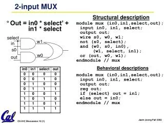
International Journal of Trend in Scientific Research and Development (IJTSRD) ISSN: 2456 International Journal of Trend in Scientific Research and Development (IJTSRD) ISSN: 2456 International Journal of Trend in Scientific Research and Development (IJTSRD) ISSN: 2456-6470 IV. Bi-STABLE PARAMETERS To verify our proposed layout designs of different logic gates on used recent specific resolution tool QCA Designer version 2.0.3 with the bistable simulation engine setup. Table 1: Bistable Simulation Parameters Parameter Value STABLE SIMULATION SIMULATION first proposed design, quantum cells 24, used design first proposed design, quantum cells 24, used design area in 0.04 µm2. To verify our proposed layout designs of different resolution tool QCA Designer version 2.0.3 with the bistable imulation Parameters Cell width Cell height QCA-Quantum-dot diameter Default Clock Time-step Relaxation time 18nm 18nm Layer Properties Properties 5nm Clock 0 1.0e-16s 1.0e-15s 3.8e- 023J 9.8e- 022J 65nm 12.90 1 1.50nm Clock-low Bistable Approximation Approximation (Options) Clock-high Radius of effect Relative permittivity Fig. 10: First proposed 2:1 multiplexer design using 24 Quantum cells 2:1 multiplexer design Layer separation using 24 Quantum cells V. The truth table of the 2-to-1 multiplexer is shown in table 2. depending on the selector (S) switching the inputs are produced at outputs , i.e., D switched to the output for S=0 and S=1 respectively . Thus, the Boolean expression for the output becomes D0 when S=0 and output is D1 when S=1. From the truth table the Boolean expression of the output Y is given as: ? ? ???̅? ??? PROPOSED DESIGN multiplexer is shown in table 2. depending on the selector (S) switching the inputs are produced at outputs , i.e., D0 , D1 and are switched to the output for S=0 and S=1 respectively . Thus, the Boolean expression for the output becomes when S=1. From the truth table the Boolean expression of the output Y is (3) Table 2: Truth table for 2:1 MUX Select Inputs Output S A 0 0 0 0 1 1 1 1 Table 2: Truth table for 2:1 MUX Output B 0 1 0 1 Y 0 1 1 1 Fig. 11: Simulation Output for 2:1 multiplexer design using 24 Quantum cells Result Analysis: Selection extents: (156.19, 150.31) [228.04x162.88] = 37142.55 nm selected: 24. Fig. 11: Simulation Output for 2:1 multiplexer design using 24 Quantum cells This is because of its ability to select one signal out of many inputs. We are proposed 2:1 MUX design in figure 10 based on quantum cells shown in figure 10 figure 10 based on quantum cells shown in figure 10 Selection extents: (156.19, 150.31) This is because of its ability to select one signal out of many inputs. We are proposed 2:1 MUX design in [228.04x162.88] = 37142.55 nm2 = 0.04 µm2 Objects @ IJTSRD | Available Online @ www.ijtsrd.com www.ijtsrd.com | Volume – 2 | Issue – 6 | Sep-Oct 2018 Oct 2018 Page: 1213
International Journal of Trend in Scientific Research and Development (IJTSRD) ISSN: 2456 International Journal of Trend in Scientific Research and Development (IJTSRD) ISSN: 2456 International Journal of Trend in Scientific Research and Development (IJTSRD) ISSN: 2456-6470 Table 3: The comparative Authors Name V.A. Mardiris et al. [4] A. Roohi et al. [5] R. S. Nadooshan et al. [7] Proposed Design-1 [Fig. 10] Table 3: The comparative table for the 2:1 QCA multiplexer architectures Number of Cells Area Clock Delay Wire Crossing 56 27 26 1 [Fig. 10] 24 table for the 2:1 QCA multiplexer architectures Wire Crossing Coplanar Coplanar Coplanar Coplanar 0.07 0.03 0.02 0.03 4 3 3 2 VI. The MUX are important part of digital logical circuits and control systems. In this paper, proposed designs for QCA 2:1 MUX were reviewed. The functionality of the proposed circuits is necessary to validate the designs using the QCA Designer bistable engine [10]. The proposed design, in term of cells, has better operation compared to the other existing some designs. REFERENCES 1.Jadav Chandra Dasa & Debashis Journal of Pure & Applied Physics Vol. 54, December 2016, pp. 802-811. 2.Mrinal Goswami, Brajendra Kumar, Harsh Tibrewal, Subhra International Conference Information Management (ICBIM), 978 3264-1114/$31.00 ©2014 IEEE. 3.Hamid Rashidi , Abdalhossein Rezai, Journal Of Nano- And Electronic Physics, Vol. 9 No 1, 01012(7pp) (2017). 4.V.A. Mardiris, I. G. Karafyllidis, Int. J. Circ. Theor. Appl. 38(8), 771 (2010). 5.A. Roohi, H. Khademolhosseini, S. Sayedsalehi, K. Navi, Int. J. Comput. Sci. Issues 8(6), 55 (2011). 6.B. Sen, M. Dutta, D. Saran, B. Sikdar, Lecture Notes Comput. Sci. 7373, 350 (2012). 7.R. Sabbaghi-Nadooshan, M. Kianpour, J. Comput. Electr. 13(1), 198 (2013) 8.B. Sen, A. Nag, A. De, B.K. Sikdar, J. Comput. Sci. 11, 233 (2015) 9.Purkayastha, T., Debashis, D., Chattopadhyay, T., (2016), Ain Shams University, hosting by Elsevier, Ain Shams Engineering Journal. 10.Patidar M., Gupta N. (2019), In: Nath V., Mandal J. (eds) Proceeding of the Second Internat Conference on Microelectronics, Computing & Communication Systems (MCCS 2017). Lecture Notes in Electrical Engineering, vol 476. Springer, Singapor 11.Patidar, N., Gupta, N., Amita K., Sumant, Katiyal, S., Choudhary, K.K.,(2013), international journal of nanotechnology (IJNA), 3(2), pp. 1-8. 12.Kumar, D., Mitra, Microelectronics Journal Microelectronics Journal CONCLUSION The MUX are important part of digital logical circuits and control systems. In this paper, proposed designs for QCA 2:1 MUX were reviewed. The functionality circuits is necessary to validate the Designer bistable engine [10]. The proposed design, in term of cells, has better operation compared to the other existing some A. Roohi, H. Khademolhosseini, S. Sayedsalehi, i, Int. J. Comput. Sci. Issues 8(6), 55 B. Sen, M. Dutta, D. Saran, B. Sikdar, Lecture Notes Comput. Sci. 7373, 350 (2012). Nadooshan, M. Kianpour, J. Comput. B. Sen, A. Nag, A. De, B.K. Sikdar, J. Comput. Purkayastha, T., Debashis, D., Chattopadhyay, T., (2016), Ain Shams University, Production and Ain Shams Engineering Jadav Chandra Dasa & Debashis De, Indian Journal of Pure & Applied Physics Vol. 54, Mrinal Goswami, Brajendra Kumar, Harsh Tibrewal, Subhra Mazumdar, International Conference Information Management (ICBIM), 978-1-4799- Patidar M., Gupta N. (2019), In: Nath V., Mandal J. (eds) Proceeding of the Second International Conference on Microelectronics, Computing & Communication Systems (MCCS 2017). Lecture Notes in Electrical Engineering, vol 476. Springer, Mazumdar, on on 2014 2014-2nd Business Business and and Hamid Rashidi , Abdalhossein Rezai, Journal Of And Electronic Physics, Vol. 9 No 1, Patidar, N., Gupta, N., Amita K., Sumant, Katiyal, S., Choudhary, K.K.,(2013), international of nanotechnologyand Application G. Karafyllidis, Int. J. Circ. Kumar, D., Mitra, D., D., (2016), 53, 53, (2016), Elsevier, pp pp 90 90–104. @ IJTSRD | Available Online @ www.ijtsrd.com www.ijtsrd.com | Volume – 2 | Issue – 6 | Sep-Oct 2018 Oct 2018 Page: 1214