Relay-Based Multiplexer Assembly Guide and Binary Input Exploration
This guide details the assembly process of a Relay-Based Multiplexer using key components including EMF dampeners, LED indicators, and switch headers. Step-by-step instructions cover connecting boards, switches, and battery harnesses to effectively construct the MUX main tree. Additionally, activities are provided to engage users in understanding binary input selection, converting binary to decimal. Ideal for electronics enthusiasts looking to learn about multiplexing, relay operations, and binary systems.


Relay-Based Multiplexer Assembly Guide and Binary Input Exploration
E N D
Presentation Transcript
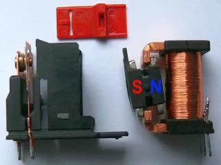
Populate Common Parts • D1Back EMF dampener • LED1 • LED2 • Output 3 pin header • R1 470ohm • R2 470ohm • SW1 3 pin header • SW2 3 pin header • RL1 Relay
Populate Sensor-MUX Qty4 • R3 TBD • R4 TBD • R5 TBD • R6 TBD • R7 TBD • R8 TBD
Populate MUX main tree Qty3 • SW1 3 pin header • SW2 3 pin header
Assemble the boards-Parts • 3 SPST switch harnesses • 1-9v battery harness • 10-3 wire connectors • 4 Sensor boards • 3 standard boards
Step one • Connect switch to topmost board SW1 • Connect SW1 to SW2 on next board down • Continue on remaining 2 boards
Step 2 • Connect switch to topmost board SW1 • Connect SW1 to SW2 on next board down • Connect first row of boards to second row as shown
Step 3 • Connect last board, switch and battery as shown.
Activity 1 • If a green light indicates a zero, • and a red light indicates a one, • What binary number will select input E? • What is that in decimal?
Activity 2 • What are the binary numbers for: • A? • B? • C? • D? • What is the decimal number for H?