Download
1 / 6
60 likes | 295 Views
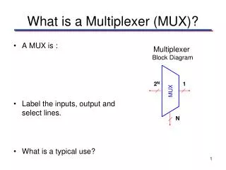
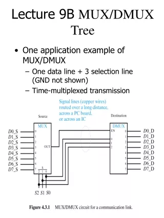
select. w1. in. s0. w0. out. 2-input MUX. Structural description. Out = in0 * select’ + in1 * select. module mux (in0,in1,select,out); input in0, in1, select; output out; wire s0, w0, w1; not (s0, select); and (w0, s0, in0), (w1, select, in1); or (out, w0, w1);

E N D
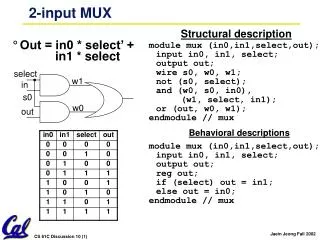
select w1 in s0 w0 out 2-input MUX Structural description • Out = in0 * select’ + in1 * select module mux (in0,in1,select,out); input in0, in1, select; output out; wire s0, w0, w1; not (s0, select); and (w0, s0, in0), (w1, select, in1); or (out, w0, w1); endmodule // mux Behavioral descriptions module mux (in0,in1,select,out); input in0, in1, select; output out; reg out; if (select) out = in1; else out = in0; endmodule // mux
in0 in2 w0 out select0 in1 w1 select1 in3 select0 4-input MUX Structural description module mux4 (in,select,out); endmodule // mux Behavioral descriptions module mux4 (in,select,out); endmodule // mux
Full Adder • S = A xor B xor Cin • Cout = AB + ACin + BCin Module FA(A, B, Cin, S, Cout);input A, B, Cin;output S, Cout;wire w0, w1, w2;xor3(S, A, B, Cin);and (w0, A, B), (w1, A, Cin), (w2, B, Cin);or3(Cout, w0, w1, w2); endmodule S FA Cout B Cin A
4-bit ripple carry adder Write a structural description module add4 (A,B,S,C); endmodule // add4 S0 S1 S2 S3 FA FA FA FA C A1 B1 w1 A2 B2 A3 B3 w0 w2 A0 B0 0
1-bit register module DFF (CLK,Q,D,RST); input D; input CLK, RST; output Q; reg Q; always @ (posedge CLK) if (RST) Q = 0; else Q = D; endmodule // DFF module mux (in0,in1,select,out); input in0, in1, select; output out; reg out; if (select) out = in1; else out = in0; endmodule // mux Write a structural description. reg1 RST w0 w1 DFF out in load CLK module reg1 (in,load,CLK, RST, out); endmodule // dffwe
4-bit shift register module shift4 (in,load,CLK,RST,out); input in, load, CLK, RST; output out; … endmodule // shift4 Write a structural description. RST RST RST RST reg1 reg1 reg1 reg1 in out w0 w0 w0 load CLK load load load CLK CLK CLK