Download
1 / 5
50 likes | 81 Views
NAMIKI 12 volt DC motor is used to model mathematically. L298 N hybrid motor driver is used to drive the motor. Voltage for the motor to drive to the desired angle is applied from the PWM of the motor. The best PWM value for the motor is considered by using PID controller from the Arduino processor. The actual angle of the motor is get from the optical encoders. The best gain for PID controller is get from Ziegler Nichols method and Simulink of MATHLAB software by using mathematical modelling equation of the motor. The modelling equation is get from two kinds of calculation. The first approach is from parameters estimation of the motor. The second is from first order differential equation. Then, the best PWM value is get for the position control of the motor. This motor is used for the robot arm. Ye Htet Aung | Tin Tin Hla "Modeling of DC Motor and Choosing the Best Gains for PID Controller" Published in International Journal of Trend in Scientific Research and Development (ijtsrd), ISSN: 2456-6470, Volume-3 | Issue-5 , August 2019, URL: https://www.ijtsrd.com/papers/ijtsrd26636.pdf Paper URL: https://www.ijtsrd.com/engineering/electronics-and-communication-engineering/26636/modeling-of-dc-motor-and-choosing-the-best-gains-for-pid-controller/ye-htet-aung<br>

E N D
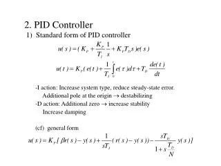
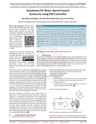
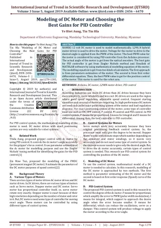
International Journal of Trend in Scientific Research and Development (IJTSRD) Volume 3 Issue 5, August 2019 Available Online: www.ijtsrd.com e-ISSN: 2456 – 6470 Modeling of DC Motor and Choosing the Best Gains for PID Controller Ye Htet Aung, Tin Tin Hla Department of Electronic Engineering, Mandalay Technological University, Mandalay, Myanmar How to cite this paper: Ye Htet Aung | Tin Tin Hla "Modeling of DC Motor and Choosing the Best Gains for PID Controller" Published in International Journal of Trend in Scientific Research and Development (ijtsrd), ISSN: 2456- 6470, Volume-3 | Issue-5, August 2019, pp.1278-1282, https://doi.org/10.31142/ijtsrd26636 Copyright © 2019 by author(s) and International Journal of Trend in Scientific Research and Development Journal. This is an Open Access article distributed under the terms of the Creative Commons Attribution License (CC (http://creativecommons.org/licenses/by /4.0) For PID control system, the mathematical modelling of the motor is need. DC motor drives with exact positioning system are very suitable for robot systems. II. Related Work Thida Aung, proposed gripper control with dc motor by using PID control. It controls the dc motor’s angle accurately for the gripper’s force control. It use parameter estimation of the dc motor for modelling purpose and use the Ziegler Nichols’ tuning method for identifying the gains for the PID control.[1] Zin Maw Tun, proposed the modelling of the PMDC (permanent magnet DC motor). It estimate the parameters of the DC motor purposes of speed control.[2] III. Background Theory A.Various Types of Motors There are two types of motor drives AC motor drives and DC motor drives. In DC drives, there are various types of motors such as Servo motor, Stepper motor and DC motor. Servo motor has proportional controller itself, so, servo motor rotate very exactly. Stepper motor is exact because of their high resolution depending on the number of stator and rotor in it. But, DC motors need some type of controller for moving exact angle. These motors can be controlled by using different types of control system. ABSTRACT NAMIKI 12 volt DC motor is used to model mathematically. L298_N hybrid motor driver is used to drive the motor. Voltage for the motor to drive to the desired angle is applied from the PWM of the motor. The best PWM value for the motor is considered by using PID controller from the Arduino processor. The actual angle of the motor is get from the optical encoders. The best gain for PID controller is get from Ziegler Nichols method and Simulink of MATHLAB software by using mathematical modelling equation of the motor. The modelling equation is get from two kinds of calculation. The first approach is from parameters estimation of the motor. The second is from first order differential equation. Then, the best PWM value is get for the position control of the motor. This motor is used for the robot arm. KEYWORDS: Arduino, DC motor, L298N motor driver, PID control I. INTRODUCTION According Industries use more DC drives than AC drives because they have more simplicity, more reliability and less cost. DC drives are used in the region where good speed regulation, adjustable speed control, frequent starting operation and reversal of motor are requiring. So, high performance DC motors are need such as for exact positioning system of the motor and load regulation response. For exact positioning system of the motor, some type of controller must use such as ON_OFF control, P control, PI control and PID control. In PID control system, P means for proportional, I means for integral and D means for differential. Among then, the best controller is PID controller. B.Control Systems for Motors Servo motors work very accurately because they have original positioning feedback control system. So, the processor must only give the degree to be moved. Stepper Motor works with minute steps which number depending on the armature and stator windings, so it moves very accurately and do not need some type of control system. So the microprocessor needs to give only the desired angle. But, to drive the dc motor accurately, certain types of control system is needed. This research use PID control system for controlling the position of the DC motor. C.Modeling of DC Motor To use the control system, mathematical model of a DC motor is needed to calculate. In this research, modelling of the DC motor is approached by two methods. The first method is parameter estimating of the DC motor and the second is based on first order response (Speed) curve of the DC motor. D. PID Control System The proposed PID control system is used in this research to control the degree of the dc motor. P means for proportional, which amplify the error to PWM (pulse width modulation), I means for integral, which support to approach the desire angle when the error become smaller. D means for differential, which can reduce the oscillations, serve as a dumper. This control system will produce voltage to apply the motor according to the error angle. IJTSRD26636 BY 4.0) @ IJTSRD | Unique Paper ID – IJTSRD26636 | Volume – 3 | Issue – 5 | July - August 2019 Page 1278
International Journal of Trend in Scientific Research and Development (IJTSRD) @ www.ijtsrd.com eISSN: 2456-6470 IV. A.Block Diagram of the system Design of the Proposed System Figure1. Block Diagram of the System Ultrasonic 12_volt battery is used as power supply for the motor. The two pins of the battery are connected to motor driver’s supply and ground pins. The ground pins of battery, motor driver and Arduino microcontroller are connected together to make common ground. The output pins of the motor driver are connected to the two supply pins of the motor to give voltage and drive the motor. The supply pin of the encoder is connected to the 5-volt pin of the Arduino. The two encoder pins are connected to the pin-10 and pin- 11 of the Arduino to count pulse to know the actual position of the motor by degree. B.Flow Chart of Robotic Arm System Firstly, define the desired position of the motor to move exactly. Then, the motor is start rotating. The actual position of the motor can be calculated by using the optical encoder. Then, calculate the error from subtracting the actual error from the desired error. Then, this error is converted to the PWM value by using the PID gains. And then, convert it to voltage to apply the motor by multiplication with 12 by 255, since the motor use 12 volt but the resolution of motor driver is 8-bit. So, its numerical value can have from o to 255. If the volt is positive value, the motor move clockwise direction. If the volt is negative value, the motor move anti clockwise direction. If the voltage is zero, the motor will stop from moving. Figure2. Flow Chart of the System C.Modelling of the DC Motor Figure3. Formation of the Parameters of the DC Motor 1.Parameters Estimation Method Firstly, it is need to measure the resistance and inductance of the motor. By measuring, the resistance of the motor is 6(ohm) and the inductance of the motor is 0.12 (mH). Then, it is need to calculate the electrical constant (Ke) of the motor. For the purposes of measuring the Ke, test the current, RPM (revolutions per minute), and Omega (radians per seconds) by feeding various supply voltage from 2 (volt) to 12 (volt) by using the equation as ω = RPM ???∗ Then, calculate the electrical constant (Ke) by using the equation Ke = By calculating using the equation, get the electrical constant (Ke) of the motor as 0.011. Then it is need to calculate back EMF constant (Kb). To calculate the back EMF constant (Kb), it is need to measure π??? ?????? ??? ? ??? ?? ???∗ ??? ??? ? ???∗ (1) ???? ω (2) @ IJTSRD | Unique Paper ID – IJTSRD26636 | Volume – 3 | Issue – 5 | July - August 2019 Page 1279
International Journal of Trend in Scientific Research and Development (IJTSRD) International Journal of Trend in Scientific Research and Development (IJTSRD) @ www.ijtsrd.com www.ijtsrd.com eISSN: 2456-6470 the stall current and stall voltage by pulling with loads to the motor until the rotating shaft stop with various supply while the mass and distance of the load is measured. Then calculate the stall torque by using the equation as T(stall) = Mass ∗ Distance And then, calculating the back EMF constant (Kt) by using the equations as Kt = By calculation like this, get the back EMF constant as 0.0105. Then, by using these parameters, calculate coefficient by using the equation B = By using this equation, get the value of the friction coefficient as B=0.0000004592. Then, calculate the value of time constant. To calculate the time constant, run the motor and get the s stable speed is steady state speed. The steady state speed for this research is 120RPM. 63.2% of the 120 RPM is 71 RPM. The time from 0 RPM rising point to 71 RPM is the time constant. For this system, the time constant Then, calculate the moment of inertia (J) by using the equation J = ? By using the equation, get the value of moment of inertia (J) as 0.0000003377. Then, get the values of all parameter of the DC motor as follows. TABLE1 Parameters of the m Parameters of the motor the stall current and stall voltage by pulling with loads to the motor until the rotating shaft stop with various supply while the mass and distance of the load is measured. Then The closed loop block diagram of the s The closed loop block diagram of the system is ation as (3) And then, calculating the back EMF constant (Kt) by using ?(?????) ?(?????)∗????????? (4) By calculation like this, get the back EMF constant as 0.0105. Then, by using these parameters, calculate the friction ??∗? ω (5) By using this equation, get the value of the friction coefficient Figure4. Closed Loop Block Diagram of the System Figure4. Closed Loop Block Diagram of the System It is need to design the transfer function of the controller. In this research, it is designed by using PID controller. Firstly, assume the controller is only included P gain. It is need to design the transfer function of the controller. In this research, it is designed by using PID controller. Firstly, assume the controller is only included P gain. So the closed loop transfer function of the system becomes T.F = Assume H(s) =1 So, the close loop transfer function becomes T.F = ?.????????????.?????????. By using Routh-Hurwitz stability criterion, Getting the values as Kcr = 4.2 and Pcr = 0.088. For PID control system, the gains are Kp = 0.22Kcr Ki = Pcr/2 Kd = Pcr/3 By using this equations, the values of PID gains are Kp=0.75, Ki=0.045 and Kd=0.03. 2.Modelling of the DC Motor Based on First Response (Speed) Curve Response (Speed) Curve Then, calculate the value of time constant. To calculate the time constant, run the motor and get the speed graph. The stable speed is steady state speed. The steady state speed for this research is 120RPM. 63.2% of the 120 RPM is 71 RPM. The time from 0 RPM rising point to 71 RPM is the time constant. For this system, the time constant τ is 0.021 sec. , calculate the moment of inertia (J) by using the transfer function of the system becomes ????(?) ??????(?)?(?) (9) So, the close loop transfer function becomes τ(???????) (6) ?.?? .??????????.????? (10) By using the equation, get the value of moment of inertia (J) as 0.0000003377. Then, get the values of all parameter of the Hurwitz stability criterion, s Kcr = 4.2 and Pcr = 0.088. For PID control system, the gains are (11) (12) No Parameters Values Unit (13) R? 1 6 Ohm By using this equations, the values of PID gains are Kp=0.75, L? 2 0.12 mH Ke 3 0.01 N.m/A Modelling of the DC Motor Based on First Order Kt 4 0.01 V.sec/rad 5 B 0.000000459 N.m.sec/rad J?? 6 0.0000003577 Kg.m? The open loop transfer function of the dc motor for speed control is ω(?) ?(?)= ?? (????)(????)????? is the motor only transfer function. And convert the (0 to 255) PWM range to (0 to 12) voltage range multiplying by the values of The open loop transfer function of the dc motor for speed ?? ?? ???∗??? ??∗ 2 (7) (????)(????)?????∗ is the motor only transfer function. And convert the (0 to 255) PWM range to (0 to 12) voltage range Figure5. Speed Curve of the Motor 5. Speed Curve of the Motor The open loop transfer function of the motor for speed control is G(s) = Where, c is the ratio of the steady state speed value of the motor to the input voltage. The steady state the motor is 120 RPM and the input voltage is 12v, so the value of c is 10. As a universal truth, the response of the dc motor will get steady state value at the value as motor will get steady state value at the value as4τ. The ?? ???. And convert the degree The open loop transfer function of the motor for speed . And convert the degree ??? ??.And, range to radium range by multiplying with multiplying with 2 because of the using encoder type. By substituting the values of the parameters of the motor to the equation, the equation change to the following equations. ω(?) ?(?)= range to radium range by multiplying with 2 because of the using encoder type. By substituting the values of the parameters of the motor to the equation, the equation change to the following equations. ? τ??? (14) Where, c is the ratio of the steady state speed value of the motor to the input voltage. The steady state speed value of the motor is 120 RPM and the input voltage is 12v, so the value of c is 10. As a universal truth, the response of the dc ?.??? ?∗(?.????????????.?????????.?????????) ) (8) @ IJTSRD | Unique Paper ID – IJTSRD26636 26636 | Volume – 3 | Issue – 5 | July - August August 2019 Page 1280
International Journal of Trend in Scientific Research and Development (IJTSRD) International Journal of Trend in Scientific Research and Development (IJTSRD) @ www.ijtsrd.com www.ijtsrd.com eISSN: 2456-6470 motor will get the steady state value at 0.28 milliseconds. So the value of time constant is 0.007. So, the transfer function of the motor becomes ω(?) ?(?)= And then, the angular response of the dc motor becomes θ(?) ?(?)= Firstly, set only P gain for the system. The closed loop transfer function of the dc motor is KcG(s) 1 + KcG(s)H(s) So, the characteristic equation for this system, 10Kc = 0. By using Routh-Hurwitz stability criterion, the value of K must be the same or greater than zero. By sequential tuning with MATLAB, we get the value of Kc as 1.Then, substituting the value of Kc to the characteristic equation and compare to s?+ 2ζω?+ ω? getting the values asω?= 37.8,p??= control system, Kp = 0.6Kc Ki = 0.5Pcr Kd = 0.125Pcr The values of the gains are Kp=0.6, Ki=0.083 and Kd=0.02. D.Result and Discussions 1.Modelling Based on Parameters Estimation Modelling Based on Parameters Estimation motor will get the steady state value at 0.28 milliseconds. So, the value of time constant is 0.007. So, the transfer function ?? ?.????? (15) And then, the angular response of the dc motor becomes ?? ?∗(?.????? ) (16) Firstly, set only P gain for the system. The closed loop Figure9. Step Response Figure9. Step Response So, the characteristic equation for this system, 0.007s?+ s + Hurwitz stability criterion, the or greater than zero. By sequential tuning with MATLAB, we get the value of Kc as 1.Then, substituting the value of Kc to the characteristic ? . By comparing, = 0.166. For PID ? ? ?π ω?= Figure10. Root Locus Figure10. Root Locus (17) 2.Modelling Based on First Order Response (Speed) Curve Modelling Based on First Order Response (Speed) (18) (19) The values of the gains are Kp=0.6, Ki=0.083 and Kd=0.02. Figure11. Open Loop Speed Transfer Function Figure11. Open Loop Speed Transfer Function Figure6. Open Loop Speed Transfer Function Figure6. Open Loop Speed Transfer Function Figure12. Open Loop Angular Transfer Function Figure12. Open Loop Angular Transfer Function Figure7. Open Loop Angular Transfer Function Loop Angular Transfer Function Figure13. Close Loop Angular Transfer Function with PID Controller PID Controller Figure13. Close Loop Angular Transfer Function with Figure8. Closed Loop Angular Transfer Function with PID Controller Figure8. Closed Loop Angular Transfer Function with @ IJTSRD | Unique Paper ID – IJTSRD26636 26636 | Volume – 3 | Issue – 5 | July - August August 2019 Page 1281
International Journal of Trend in Scientific Research and Development (IJTSRD) International Journal of Trend in Scientific Research and Development (IJTSRD) @ www.ijtsrd.com www.ijtsrd.com eISSN: 2456-6470 Figure14. Step Response Figure14. Step Response Figure19. Experiment of the motor 19. Experiment of the motor V. The DC motor can’t rotate exactly without any controller. If the motor is needed to move with exact speed and degree, some type of motor is needed. To get the best gain for the controller, it is needed to calculate the mathematical modelling equation for the motor. The gain for the controller can be changed according to the size of the desired angle or speed. It is better if fuzzy controller i with the PID controller. VI. Conclusion Modelling of the motor needs exact data. the six parameters of the DC motor. The values of the resistance and inductance of the motor can be measured by using RLC meter. The value f get from RC filter circuit graph. Other parameters can be measured from equation by using the values getting from supplying various voltages. And then, the gain for the PID controller will get by using Ziegler Nichols’ method modelling is based on first order differential equation. These values can be get from velocity output of the voltage input. The best gains for the PID controller can also get from Ziegler Nichols’ method and Simulink with MATHLAB. ACKNOWLEDGEMENT Author would like to express special thanks to Dr. Tin Tin Hla for her valuable suggestion, supervision, encouragement and sharing her experience to write this research. And also, the author is also thankful to all of his teachers from Department of Electronic Technological University. REFERENCES [1]Thida Aung, Mandalay Technological university, Contact Force Control of a Robot Gripper Using Force Sensor Feedback, 2018. Sensor Feedback, 2018. Discussion The DC motor can’t rotate exactly without any controller. If the motor is needed to move with exact speed and degree, needed. To get the best gain for the controller, it is needed to calculate the mathematical modelling equation for the motor. The gain for the controller can be changed according to the size of the desired angle or speed. It is better if fuzzy controller is cascaded together Figure15. Root Locus 3.Results from motor Modelling of the motor needs exact data. Measure and test the six parameters of the DC motor. The values of the resistance and inductance of the motor can be measured by using RLC meter. The value for the torque of the motor can get from RC filter circuit graph. Other parameters can be measured from equation by using the values getting from supplying various voltages. And then, the gain for the PID controller will get by using Ziegler Nichols’ method. Another modelling is based on first order differential equation. These values can be get from velocity output of the voltage input. The best gains for the PID controller can also get from Ziegler Nichols’ method and Simulink with MATHLAB. Figure16. Speed Curve of the Motor Figure16. Speed Curve of the Motor Author would like to express special thanks to Dr. Tin Tin Hla for her valuable suggestion, supervision, encouragement and sharing her experience to write this research. And also, the author is also thankful to all of his teachers from Electronic Engineering, Engineering, Mandalay Mandalay Thida Aung, Mandalay Technological university, Contact Force Control of a Robot Gripper Using Force Figure17. Angle curve of the motor motor [2]Zin Maw Tun, Mandalay Technological university, PMDC motor modeling and Parameter Identification for Control Purpose, 2018. for Control Purpose, 2018. Zin Maw Tun, Mandalay Technological university, eling and Parameter Identification [3]Mo Mo aung, Mandalay Technological University, Design and Implementation of Color Sorting Robotic Arm, 2018. Mo Mo aung, Mandalay Technological University, Design and Implementation of Color Sorting Robotic [4]Fu Gonzalet and Lee, Robotics: Control, Sensing, Vision and Intelligent. Fu Gonzalet and Lee, Robotics: Control, Sensing, Vision Figure18. Actual Angle and Error angle of the motor Figure18. Actual Angle and Error angle of the motor [5]Tan Kok Kiong Andisubjana Putra, PID control method. g Andisubjana Putra, PID control method. [6]Prof. Yon_Ping Chen, Dynamic System Simulation and Implementation. Prof. Yon_Ping Chen, Dynamic System Simulation and @ IJTSRD | Unique Paper ID – IJTSRD26636 26636 | Volume – 3 | Issue – 5 | July - August August 2019 Page 1282