Download
1 / 3
30 likes | 55 Views
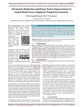
This article describes the topology of a DC DC converter operating in switching mode on off . During the completion of the switching cycle, the entire current flow may be resolved and the load may be left. Under these conditions, the initial conventional upconverter switches are heavily loaded and result in large power losses. Switches with boost converters provide low loss, high output voltage, high efficiency, small size, reduced electromagnetic interface EMI , and low voltage components for power supplies. Prof B. Sampath Kumar | Mr. P. B Vyavahare "Harmonics Reduction and Power Factor Improvement of Switch Mode Power Supply by Using Zeta Converter" Published in International Journal of Trend in Scientific Research and Development (ijtsrd), ISSN: 2456-6470, Volume-3 | Issue-4 , June 2019, URL: https://www.ijtsrd.com/papers/ijtsrd23891.pdf Paper URL: https://www.ijtsrd.com/engineering/electrical-engineering/23891/harmonics-reduction-and-power-factor-improvement-of-switch-mode-power-supply-by-using-zeta-converter/prof-b-sampath-kumar<br>

E N D
International Journal of Trend in Scientific Research and Development (IJTSRD) Volume: 3 | Issue: 4 | May-Jun 2019 Available Online: www.ijtsrd.com e-ISSN: 2456 - 6470 Harmonics Reduction and Power Factor Improvement of Switch Mode Power Supply by Using Zeta Converter Prof B. Sampath Kumar1, Mr. P. B Vyavahare2 1Assistant Professor, 2Student 1,2Department of Electrical Engineering, FTCCOER Sangola, Solapur University, Solapur, Maharashtra, India How to cite this paper: Prof B. Sampath Kumar | Mr. P. B Vyavahare "Harmonics Reduction and Power Factor Improvement of Switch Mode Power Supply by Using Zeta Converter" Published in International Journal of Trend in Scientific Research and Development (ijtsrd), ISSN: 2456- 6470, Volume-3 | Issue-4, June 2019, pp.697-699, URL: https://www.ijtsrd.c om/papers/ijtsrd23 891.pdf Copyright © 2019 by author(s) and International Journal of Trend in Scientific Research and Development Journal. This is an Open Access article distributed under the terms of the Creative Commons Attribution License (CC BY 4.0) (http://creativecommons.org/licenses/ by/4.0) K. Karanki et al [1] The importance of on / off conditions was used to increase the efficiency of parallel power supplies unit (PSU), such as large enterprise servers, by applying light loads with high power factor correction (PFC) converters. A heavy server load reduces power supply efficiency and increases losses. In our proposed method, a light load approach is used to reduce losses such as including capacitors and core losses. Improve expected performance. Here, the PFC converter operates at a frequency of 60 Hz at a light-load-only frequency, and the two parallel power supplies are alternately connected, reducing harmonic distortion and improving power supply (server) efficiency. Kian Hoong Kwan et al [2] Linear voltage recovery (LVR) and total harmonic distortion enhancement (THDI) methods are Power Factor (PF) and Total Harmonic Distortion (THD) for a wide range of line voltage Corrector Control Power Factor Corrector (PFC) for improvement. LVR determines the RMS voltage of the input line and generates a digital equivalent code for THDI to optimize the THD by adjusting the on-time value with different line voltages. In addition, LVR and THDI provide a forward link path, reducing the feedback voltage ripple and further improving THD. A. Mokhtatpour and H.A. Shayanfar [3] This article proposes to switch ON-OFF the power factor correction (PFC) ABSTRACT This article describes the topology of a DC-DC converter operating in switching mode (on / off). During the completion of the switching cycle, the entire current flow may be resolved and the load may be left. Under these conditions, the initial conventional upconverter switches are heavily loaded and result in large power losses. Switches with boost converters provide low loss, high output voltage, high efficiency, small size, reduced electromagnetic interface (EMI), and low voltage components for power supplies. Keywords: Multiple outputs, power factor corrected Zeta converter, power quality, switched mode power supply (SMPS), unity power factor I. INTRODUCTION Today, existing server models produced low-voltage outputs with series- connected amplifiers. However, the expected high voltage was achieved by a parallel DC boost converter. Most existing transducers, such as resonant inverse sequential bridge and push-pull transducers, are not recommended because they add wave effects to the current flowing from the fuel cell compared to a conventional boost converter. In the proposed DC boost converter, a constant phase shift of 180 ° has less effect on the ripple effect. Compared to a conventional upconverter, various aspects are analyzed, such as the design aspect, steady state, transient response, device selection, operating principle, gate circuit, etc. II. Literature Survey There are many definitions of various control of power factor correction available in the literature. converter to improve the light load efficiency of the parallel power supply (PSU) for the server. The proposed scheme controls the PFC cascade of two parallel power supplies in sequence only at low load at 60 Hz in one AC cycle. This reduces load-independent losses such as capacitive switching and core losses and improves the efficiency at low loads without degrading performance at high loads. Furthermore, the proposed scheme reduces harmonic distortion by reducing the area of discontinuous modes. J.A. Munoz et al [4] The analysis, design and implementation of a microcontroller based electronic ballast for supplying metal halide (MH) lamps is presented. The proposed topology is based on the integration of a double circuit and an inverse converter, the first providing power factor correction and the second controlling the lamp power. The lamp is supplied with low square wave current, which is a convenient way to avoid acoustic resonance in high intensity gas discharge lamps. Since both converters operate in discontinuous conduction mode, a single high-frequency switch simplifies control. III. Proposed System In many of the pulse-width modulated topologies of the dc converter in the proposed system, the controlled switches operate in the switching mode, which is required to turn the IJTSRD23891 @ IJTSRD | Unique Paper ID - IJTSRD23891 | Volume – 3 | Issue – 4 | May-Jun 2019 Page: 697
International Journal of Trend in Scientific Research and Development (IJTSRD) @ www.ijtsrd.com eISSN: 2456-6470 full load current on and off during each switching cycle. Under these conditions, the switch is subject to high switching loads and power loss. Recently, the advantages of high-frequency operation, high efficiency, small size, low weight, reduced electromagnetic interference (EMI), and low voltage components have led to increased interest in the use of resonant DC-DC converters. A PID based Zeta converter generates a PWM signal for a switch with a reference input. Its converter outputs an SMPS source with improved PFC. V. The efficiency of the proposed P-I-D control has been examined by computer simulation using MATLAB and associated toolbox “SIMULINK” and “Power System Block Simulation Circuit Diagram Fig.2 Matlab Simulation Diagram Fig 1.Block Diagram of Proposed System IV. In a proposed system used for Zeta Converter, P-I-D Controller, SMPS, Bridge Rectifier. ZETA CONVERTER: Proposed System Module and Devices Fig.3 Waveform of AC Supply Voltage of Line Current Before Application of Zeta Converter Fig.2 Zeta Converter Topology The zeta converter is a fourth-order non-linear system and can be thought of as a delayed converter for energy input and as a buck-boost-buck converter at output. P-I-D Controller: P-I-D controllers have optimal control dynamics including zero steady-state error, fast response (short rise time), no vibration, and higher stability. The need to use a differential gain component in addition to the PI controller is to eliminate the overshoot and oscillations that occur in the output response of the system. One of the main advantages of P-I-D controllers is that they can be used in higher-order processes that involve multiple energy storage. To observe the above basic effects of proportional, integral, and derivative gains on system response, see the following simulation created in MATLAB in continuous time using transfer functions and unit step inputs. The result is how to tune. SMPS: Switching Power Supply (SMPS) for converting a DC input voltage to a regulated DC output voltage. However, in the case of an SMPS operating with an input power supplied from an AC network, the DC converter can only work with a DC input, therefore the input voltage is reduced to the desired value in the first stage, a high-frequency transformer circuit used in SMPS using an output capacitor rectifier, much smaller in size and weight compared with the low- frequency transformer in the linear power supply circuits. Fig.4 Waveform of AC Supply Voltage of Line Current After Application of Zeta Converter Fig.6 Harmonics of AC Supply After Application of Zeta Converter Fig.6 Waveform of Output DC Voltage @ IJTSRD | Unique Paper ID - IJTSRD23891 | Volume – 3 | Issue – 4 | May-Jun 2019 Page: 698
International Journal of Trend in Scientific Research and Development (IJTSRD) @ www.ijtsrd.com eISSN: 2456-6470 From fig.3 to 5, we have been observed that THD of main input supply line is reduced to zero as well as power factor has been improved to unity. Thus the by use of this SMPS will reduce adverse effect of low power factor as well as harmonics. This proposed system gives supply voltage and current in phase with each other this as a result losses will be reduced. VI. Conclusion The proposed design has a very simple scheme. This converter has higher gains and voltages, as well as lower switching current averages than traditional bi-directional buck/boost converters. In addition, due to the use of current feedback methods, heat loss can be reduced, which prolongs the service life of the switch. Discrete PID reduces current and switching frequency for high output voltage, current and switching frequency, and high output voltage. Closed-loop control takes precedence over open-loop control. Using the PID controller, you can control the switch duty cycle for high output voltage and high gain. Acknowledgement This research was supported by FTCR, Sangola, Maharashtra. We thankful to Prof. Mallareddy Chinala, HoD (EE), FTCR, Sangola for great moral support. We thank our colleagues from Fabtech College of Engg. Sangola, Solapur who provided insight and expertise that greatly assisted the research. We thank to our project guide Prof.Sampath Kumar Bodapatla for our all achievement in this project. References [1]K. Karanki, G. Geddada, M.K. Mishra, and B.K. Kumar, "A Modified Three-Phase Four-Wire UPQC Topology With Reduced DC-Link Voltage Rating," IEEE Trans. Ind. Electron., vol. 60, no. 9, pp. 35553566, Sep. 2013. [2]Kian Hoong Kwan, Ping Lam So, and Yun Chung Chu, "An Output Regulation-Based Unified Power Quality Conditioner With Kalman Filters," IEEE Trans. Ind. Electron., vol. 59, no. 11, pp. 4248-4262, Nov. 2012. [3]A. Mokhtatpour and H.A. Shayanfar, "Power Quality Compensation as Well as Power Flow Control Using of Unified Power Quality Conditioner," in Power and Energy Engineering Conference (APPEEC), 2011 Asia- Pacific, 2011, pp. 14. [4]J.A. Munoz et al., "Design of a Discrete-Time Linear Control Strategy for a Multicell UPQC," IEEE Trans. Ind. Electron., vol. 59, no. 10, pp. 37973807, Oct.2012. [5]V. Khadkikar and A. Chandra, "UPQC-S: A Novel Concept of Simultaneous Voltage Sag/Swell and Load Reactive Power Compensations Utilizing Series Inverter of UPQC," IEEE Trans. Power Electron., vol. 26, no. 9, pp. 2414-2425, 2011. [6]V. Khadkikar, "Enhancing Electric Power Quality Using UPQC: A Comprehensive Overview," IEEE Trans. Power Electron, vol. 27, no. 5, pp. 2284-2297, 2012. [7]V. Khadkikar and A. Chandra, "A New Control Philosophy for a Unified Power Quality Conditioner (UPQC) to Coordinate Load-Reactive Power Demand Between Shunt and Series Inverters," IEEE Trans. Power Del., vol. 23, no. 4, pp. 2522-2534, Oct. 2008. @ IJTSRD | Unique Paper ID - IJTSRD23891 | Volume – 3 | Issue – 4 | May-Jun 2019 Page: 699