Download
1 / 11
110 likes | 285 Views
SWITCH -MODE POWER SUPPLIES AND SYSTEMS. Lecture No 5. Silesian University of Technology Faculty of Automatic Control, Electronics and Computer Sciences Ryszard Siurek Ph.D., El. Eng. Continous/discontinuos current (magnetic flux) flow in output inductance of step-down regulator. I L.

E N D
SWITCH-MODE POWER SUPPLIES AND SYSTEMS Lecture No 5 Silesian University of Technology Faculty of Automatic Control, Electronics and Computer Sciences Ryszard Siurek Ph.D., El. Eng.
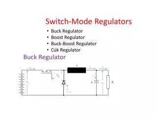
Continous/discontinuos current (magnetic flux) flow in output inductance of step-down regulator IL L T I0 I0 UIN U1 D C Ro I0cr critical current t T L L L Uwe U0 D U0 U0 U1 , U0 >U0 U0 t t1 T IL I0cr I0<I0cr
Step-down regulator output characteristic For output current exceeding critical value output voltage depends linearly on duty cycle – stable feedback loop is easy to accomplish For output current below critical value output characteristic bocomes significantly nonlinear, which makes difficult to maintain stable operation of closed feedback loop U0 UIN 0,5UIN I0 I0cr Critical current decrease may be obtained: - by increasing the switching frequency - by increasing the inductance of the output choke Step-down regulator - output voltage is always lower than the input voltage - output voltage rises to the maximum value of the input voltage in case of no-load condition - AC current component is the same for output inductor and capacitor
„Step-up” (boost) switching regulator L ID IL Io ~ D IC T UC UT UIN U0 Ro UC C U0 t T Assumptions: Diode D and transitor T are perfect (ideal) switches Series resistance of the choke L is negligible (rL= 0) Capacitance C is very large (DUc << Uo) EL EL D D EC I cycle II cycle T EC Io Io T UIN UIN T – ON, D – OFF T – OFF, D – ON
Basic waveforms in step-up switching regulator UT I cycle - equivalent circuit 0 < t < t ILmin L ~ ‘ I0 rL= 0 IL t t T ~ IT UC Ro IT ILmin UIN U0 t ILmax ~ UC << U0 IL , Calculation of IL– superposition method ILmin t ID ILmin t t IC t <<1 ~ UC t Uc(0) inductor current swing
„ UT II cycle - equivalent circuit t <t < T U0 L ~ rL= 0 IL ILmax I0 t t T ~ IT UC Ro UIN UT U0 t ILmax ~ IL UC << U0 IINAV ILmin inductor current swing t in steady state: ID t IC t Step-up regulator transfer function ~ UC t Uo > UIN
Continous/discontinuos current (magnetic flux) flow in step-up regulator inductance IIN U0 DIL IINcr g’ > g g t T Uwe from energy balance: The same as for step-down I0cr I0 Step-up regulator - output voltage always higher than the input voltage - can not operate in no-load condition (output voltage rise out of control) - high value of RMS output capacitor current
„Step-up-step-down” (flyback) switching regulator T IT ID Io IL ~ IC D UC UIN L U0 Ro UL UC C t T U0 Assumptions: Diode D and transitor T are perfect (ideal) switches Series resistance of the choke L is negligible (rL= 0) Capacitance C is very large (DUc << Uo) T D T D EC EL EC I cycle II cycle Io Io UIN Uwe EL T – ON, D – OFF T – OFF, D – ON
Basic waveforms in flyback switching regulator I cycle - equivalent circuit 0 < t < t UL IT ILmin I0 UIN t ‘ ~ IL UC t T Ro UL -U0 IT L U0 UIN ILmin ~ t UC << U0 ILmax IL inductor current swing ILmin II cycle - equivalent circuit t <t < T „ t ILmax IL I0 ILmax ID „ ~ I0=ILavr UC L Ro t U0 IC t inductor current swing in steady state: ~ UC Flyback regulator transfer function t Uc(0)
Continous/discontinuos current (magnetic flux) flow in flyback regulator inductance continuous current flow (Fm) IL critical current flow Ilmaxcr=DIL discontinuous current flow The value of energy accumulated in the inductor by the end of I cycle is constant, so current decreasing below critical value (beginning of discontinuous current flow) must result in output voltage rise. t t t1 T IT t ID I0 I0cr I0<I0cr UL UIN t U0
(1) from energy balance we obtain: (2) -U0 energy stored in the choke by the end of I cycle energy transfered to the load during the pulse repetition period T g > 0,5 from equtions (1) & (2) we obtain: g = 0,5 Uwe g < 0,5 I0cr I0 Flyback regulator - output voltage of opposite polarity, may be higher or lower than the input voltage - can not operate in no-load condition (output voltage rise out of control) - high value of RMS output capacitor current