Download
1 / 7
70 likes | 85 Views
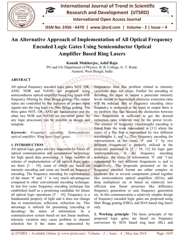
All optical frequency encoded logic gates NOT, OR, AND, NOR and NAND are proposed using semiconductor optical amplifier based ring lasers with frequency filtering by fiber Bragg grating. The output states are controlled by the injection of proper input signals into the ring laser via fiber Bragg grating. The three gates NOT, OR, AND are fundamental and the other two NOR and NAND are universal gates. So any logic processors can be possible to design and integrate. Kousik Mukherjee | Ashif Raja "An Alternative Approach of Implementation of All Optical Frequency Encoded Logic Gates Using Semiconductor Optical Amplifier Based Ring Lasers" Published in International Journal of Trend in Scientific Research and Development (ijtsrd), ISSN: 2456-6470, Volume-2 | Issue-4 , June 2018, URL: https://www.ijtsrd.com/papers/ijtsrd14320.pdf Paper URL: http://www.ijtsrd.com/physics/other/14320/an-alternative-approach-of-implementation-of-all-optical-frequency-encoded-logic-gates-using-semiconductor-optical-amplifier-based-ring-lasers/kousik-mukherjee<br>

E N D
International Research Research and Development (IJTSRD) International Open Access Journal International Open Access Journal International Journal of Trend in Scientific Scientific (IJTSRD) ISSN No: 2456 ISSN No: 2456 - 6470 | www.ijtsrd.com | Volume Alternative Approach of Implementation of All Optical Frequency 6470 | www.ijtsrd.com | Volume - 2 | Issue – 4 An Alternative Approach o Encoded Logic Ga Encoded Logic Gates Using Semiconductor Optical Amplifier Based Ring Lasers tation of All Optical Frequency Optical Amplifier Based Ring Lasers Kousik Mukherjee, Ashif Raja PG and UG Department of Physics epartment of Physics, B. B. College, G. T. Road, Asansol, West Bengal, India Kousik Mukherjee, Ashif Raja ABSTRACT All optical frequency encoded logic gates NOT, OR, AND, NOR and NAND are proposed using semiconductor optical amplifier based ring lasers with frequency filtering by fiber Bragg grating. The output states are controlled by the injection of proper input signals into the ring laser via fiber Bragg grating. The three gates NOT, OR, AND are fundamental and the other two NOR and NAND are universal gates. So any logic processors can be possible to design and integrate. Keywords:Frequency encoding; Semiconductor optical amplifier; Ring laser; logic gates. 1. INTRODUCTION All optical logic gates are very important for future all optical communication and computation technology for high speed data processing. A large number of scheme of implementation of all optical logic gates are there [1 – 10], some of which are based on intensity encoding and some are based on frequency encoding. The frequency encoding for representation of the states ‘0’ and ‘1’ is very much advantageous compared to other conventional encoding technique. In last few years frequency encoding technique has established itself as a promising candidate for future all optical logic operations [5 – 10]. Frequency is a fundamental property of light and it does not change due to transmission, reflection, refraction etc. This advantage is utilized for presenting (e decoding) the states communication system based on non linear medium, intensity variation may cause problem in channel selection but if the states are represented by selection but if the states are represented by All optical frequency encoded logic gates NOT, OR, AND, NOR and NAND are proposed using semiconductor optical amplifier based ring lasers with frequency filtering by fiber Bragg grating. The output states are controlled by the injection of proper input signals into the ring laser via fiber Bragg grating. The frequencies then this problem related to intensity ons does not exists. Further for encoding or decoding the input or output a particular intensity levels should be maintained otherwise extinction ratio will be reduced. But in frequency encoding since frequency is measured at the input or output there is o problem like that because the distinction between two frequencies is sufficient to get the desired extinction ratio whatever may be the power levels. The essence of frequency (wavelength) encoding is found from the work represented in [11] where the es of a flip flop is represented by two different . This frequency encoding for representation of the states ‘0’ and ‘1’ by two different frequencies is properly utilized in the frequencies then this problem related to intensity variations does not exists. Further for encoding or decoding the input or output a particular intensity levels should be maintained otherwise extinction ratio will be reduced. But in frequency encoding since frequency is measured at the input or output there is no problem like that because the distinction between two frequencies is sufficient to get the desired extinction ratio whatever may be the power levels. The essence of frequency (wavelength) encoding is found from the work represented in [11] where the states of a flip flop is represented by two different wavelengths λ1 and λ2. This frequency encoding for representation of the states ‘0’ and ‘1’ by two different frequencies is properly utilized in the proposals presented in [5 – implementations. In the technique, the states of information ‘0’ and ‘1’are represented by two different frequencies υ respectively. The proposals presented so far in frequency encoded format are either complex in hardware due to several components joined together like semiconductor optical amplifiers (SOA), add drop multiplexer etc or based on relatively low efficient non linear processes like difference frequency generation or sum frequency generation etc. In this communication a rela of frequency encoded logic gates are proposed using fiber Bragg grating (FBG), and SOA based ring lasers only. amental and the other two NOR and NAND are universal gates. So any logic processors can be possible to design and Frequency encoding; Semiconductor optical amplifier; Ring laser; logic gates. All optical logic gates are very important for future all optical communication and computation technology for high speed data processing. A large number of scheme of implementation of all optical logic gates 10], some of which are based on intensity encoding and some are based on frequency encoding. The frequency encoding for representation of the states ‘0’ and ‘1’ is very much advantageous compared to other conventional encoding technique. In last few years frequency encoding technique has established itself as a promising candidate for future 10, 12] for logic gate entations. In the frequency frequency encoding encoding technique, the states of information ‘0’ and ‘1’are represented by two different frequencies υ1 and υ2 respectively. The proposals presented so far in frequency encoded format are either complex in al components joined together like semiconductor optical amplifiers (SOA), add drop multiplexer etc or based on relatively low efficient non linear processes like difference frequency generation or sum frequency generation etc. In this communication a relatively simpler design of frequency encoded logic gates are proposed using fiber Bragg grating (FBG), and SOA based ring lasers 10]. Frequency is a fundamental property of light and it does not change due to transmission, reflection, refraction etc. This advantage is utilized for presenting (encoding or decoding) the states communication system based on non linear medium, intensity variation may cause problem in channel of of information. information. In In a a 2. Working principle: The basic principle of the proposed logic gates are based on frequency conversion by SOA based ri conversion by SOA based ring laser (RL) and The basic principle of the proposed logic gates are based on frequency @ IJTSRD | Available Online @ www.ijtsrd.com @ IJTSRD | Available Online @ www.ijtsrd.com | Volume – 2 | Issue – 4 | May-Jun 2018 Jun 2018 Page: 1659
International Journal of Trend in Scientific Research and Development (IJTSRD) ISSN: 2456-6470 frequency multiplexing based on optical filtering property of fiber Bragg grating (FBG). desired frequency is reflected and other frequencies are transmitted in a different path. In the figure 2 the FBG based multiplexer is shown. For proper frequency routing (multiplexing) the position of the circulator is very important. 2.1 Operation of the ring laser: The ring laser using SOA is shown in the figure 1. It uses an SOA acting as laser gain medium, Fabry – Perot filter (FPF) used for frequency selection, and isolator. The working of this type of ring laser is explained in [13] and is used to implement flip flop in [14]. The laser starts lasing if the gain of the SOA is higher than the lasing threshold of the ring laser. A high intensity external light is injection causes the gain to be saturated and thus a reduction of the gain below the threshold value causes the lasing to stop. An external light of sufficient intensity (~ 2 mW) can suppress the lasing [14]. Figure 2. FBG based Multiplexer In the figure 2, the grating period Δ and neff satisfy the Bragg condition for the frequency υ4. So the corresponding wavelength λ4 = 2 neff Δ will be reflected and the other signals are transmitted. 3. Implementation of different logic gates: The frequency encoded logic gates recently finds applications in varieties of applications like designing logic gates, half adder and full adder [7, 18], encryption/decryption system [19], ROM [20], Multiplexer [21], etc. So designing frequency encoded logic is very important in all optical communication and computation. In this section the implementation of frequency encoded logic gates are presented using SOA based ring laser for the first time. Figure 1. Ring Laser When the input is not present the laser lases at its lasing frequency say at υ. But if there is an input light of sufficient intensity to cause gain saturation at a different frequency from υ (say υ’), the lasing stops. In this communication this property is utilized to implement frequency encoded logic gates. The basic element for the implementation of the logic gate is the ring laser shown in the figure1 which lases at a particular frequency. For the routing of the frequencies the FBG filter based multiplexer as shown in the figure 2 will be used. The frequency encoding technique for the representation of the states ‘0’ and ‘1’ is used. The ‘0’ state is represented by a frequency υ1, and ‘1’ state is represented by another frequency υ2. The truth table for the frequency encoded different logic gates are shown in the table 1. 2.2 Operation of Fiber Bragg Grating: A fiber Bragg grating has a periodical perturbation of the refractive index in the fiber core, acts as a frequency selective filter [15]. Fiber Bragg gratings are made using an ultraviolet source and electron beam phase mask [16] or by irradiating two ultraviolet beams transversely in the fiber core to produce interference pattern in the fiber core. When signals of more than one frequency encounters the grating, the frequency which is phase matched to the Bragg reflection condition is reflected and the rest are transmitted. The Bragg condition for reflection is given by λB = 2 neff Δ, where Δ is the grating period and neff is the effective refractive index of the core. The reflectance at the Bragg wavelength λB is given by R = tanh2(kL) where kL is the coupling strength is the product of coupling coefficient k and grating length L [15, 17]. For kL = 3, the value of R is 0.98 and for kL = 5, R = 0.999 etc. So by adjusting Δ, kL one can achieve the reflection of the desired frequency. In this communication the FBG is used for such frequency multiplexing i.e. a Table 1: Truth table of the NOT gate Input Output A Ã υ1 (0) υ2 (1) υ1(0) υ2(1) @ IJTSRD | Available Online @ www.ijtsrd.com | Volume – 2 | Issue – 4 | May-Jun 2018 Page: 1660
International Journal of Trend in Scientific Research and Development (IJTSRD) ISSN: 2456-6470 RL4 will not receive any signal from the ring laser RL2. Therefore RL4 will lase at frequency υ2 in this condition indicating an output ‘1’or high. This corresponds to the NOT operation from’0’ to ‘1’. Table 2: Truth table of OR, AND, NOR, NAND gates Inputs A B 0(υ1 ) 0(υ1 ) 0(υ1 ) 1(υ2 ) 1(υ2 ) 0(υ1 ) 1(υ2 ) 1(υ2 ) Outputs OR 0(υ1 ) 1(υ2 ) 1(υ2 ) 1(υ2 ) AND NOR NAND 0(υ1) 0(υ1) 0(υ1) 1(υ2) 0(υ1 ) 1(υ2 ) 0(υ1 ) 0(υ1 ) 1(υ2 ) 1(υ2 ) 1(υ2 ) 0(υ1 ) Case 2: When the input A is a signal of frequency υ2 it is directed towards the FBG tuned to reflect frequency υ1. So in this condition the signal of frequency υ2 will pass through the FBG and stop lasing of the ring laser RL1. At the same time the ring laser RL3 receives no signal and hence lase to suppress the lasing of the ring laser RL4. Since RL1 stops lasing RL2 will lase at frequency υ1. So the final output is a signal of frequency υ1. This corresponds to the frequency NOT operation from ‘1’ to ‘0’ i.e. from high to low. 3.1 NOT gate: The frequency encoded NOT gate shown in the figure 3 consists of four ring laser RL1, RL2, RL3 and RL4, one FBG selected to reflect frequency υ1, and a circulator. The ring lasers RL1 and RL3 lase at frequency υ3, the ring laser RL2 at frequency υ1and RL4 at υ2.The output of the ring laser RL1 is coupled to the input of the ring laser RL2 and the output of the ring laser RL3 is coupled to the input of the ring laser RL4. So when the ring laser RL1 lases, the ring laser RL2 does not lase. Similarly when the ring laser RL3 lases, RL4 does not. If the ring lasers RL1 and RL3 receive input signals then they stop lasing and as a result RL2 and RL4 start lasing. The circuit is so designed that both the ring lasers RL2 and RL4 does not lase simultaneously and this is possible due to the presence of circulator and FBG. In the circuit A is input and A is the inverted output. The circuit will give output at frequency υ2 (i.e. ‘1’) when the input is a signal of frequency υ1 (i.e. ‘0’) and will give output at frequency υ1 when the input is a frequency υ2. When there is no input signal applied, i.e. A is neither a signal of frequency υ1 nor a signal of frequency υ2, ring lasers RL1 and RL3 lase nor thus RL2 and RL4 stop lasing. So there is no output. 3.2 OR gate: The implementation of the OR gate requires five ring lasers RL1, RL2, RL3, RL4, RL5 and two fiber Bragg grating FBG1 and FBG2 both designed to reflect frequency υ1. Among these RL1 and RL2 lase at frequencies υ2 and υ1 respectively, and all the other ring lasers RL3, RL4 and RL5 lase at frequency υ3. A and B are two frequency encoded inputs and are coupled through circulators and FBGs (both FBG1 and FBG2 are selected to reflected frequency υ1). The coupled signal is injected into the ring laser RL3. The output of the ring laser RL3 is coupled to ring laser RL1. The signals emerging from other ports of the circulator are injected into the ring lasers RL4 and RL5 and output of them are coupled and injected into the ring laser RL2. The outputs of RL1 and RL2 are coupled to get the final OR output. The circuit is so designed that the ring lasers RL1 and RL2 do not lase simultaneously. In the figure 4, the circuit diagram of the OR gate is shown. 3. NOT gate Figure Let us now explain the operation of the Not gate. Case 1: When the input A is a signal of frequency υ1, it is directed towards the FBG by the circulator. The FBG is tuned to reflect the frequency υ1 so the signal will be reflected back to the circulator and will be directed towards the ring laser RL3 by the circulator. So in this condition the ring laser RL1 will receive no signal but the ring laser RL3 will receive a signal of frequency υ1. Therefore the RL1 will lase at frequency υ3 and cause RL2 to get gain saturated. So there is no signal at frequency υ1 at the output. But since RL3 receives a signal it stops lasing and hence Figure 4. OR gate Let us explain the operation of the OR gate. Depending on the frequencies in the inputs A and B there may be four different cases: Case 1: When both the inputs A and B are signals of frequency υ1, they will be reflected by the FBG1 and FBG2 respectively. The circulators will direct them @ IJTSRD | Available Online @ www.ijtsrd.com | Volume – 2 | Issue – 4 | May-Jun 2018 Page: 1661
International Journal of Trend in Scientific Research and Development (IJTSRD) ISSN: 2456-6470 towards the ring lasers RL4 and RL5. These signals suppress the ring lasers RL4 and RL5. So the ring laser receives no input and hence lases at frequency υ1. At this time the ring laser RL3 does not receives any input so lases at a frequency υ3 and this signal of frequency υ3 suppresses the laser RL2. So from the output of the ring laser RL1, the final output is υ1. This corresponds to the OR operation ‘0’ OR ‘0’ = ‘0’ in frequency encoded format. signals emerging from other ports of the circulator are injected into the ring lasers RL4 and RL5 and output of them are coupled and injected into the ring laser RL2. The outputs of RL1 and RL2 are coupled to get the final AND output. The circuit is so designed that the ring lasers RL1 and RL2 do not lase simultaneously. Case 2: When the input A is a signal of frequency υ1 and B is a signal of frequency υ2, the signal of frequency υ1 after reflecting back from FBG1 is directed towards the ring laser RL4 and suppress the lasing of RL4. The signal of frequency of υ2 in the input B passes through the FBG2 and suppresses the lasing of RL3. So in this condition RL3 and RL4 stop lasing and RL5 lases. The output of the ring laser RL5 suppresses the lasing of RL2. The laser RL1 lases at frequency υ2 and hence the final output is υ2 i.e. high. Figure 5.AND gate Let us explain the operation of the AND gate by considering four different input conditions in A and B. Case 3: When the input A is a signal of frequency υ2 and B is a signal of frequency υ1, the signal of frequency υ1 after reflecting back from FBG2 is directed towards the ring laser RL5 and suppress the lasing of RL5. The signal of frequency of υ2 in the input A passes through the FBG1 and suppresses the lasing of RL3. So in this condition RL3 and RL5 stop lasing and RL4 lases. The output of the ring laser RL4 suppresses the lasing of RL2. The laser RL1 lases at frequency υ2 and hence the final output is υ2 i.e. high. Case 1: When both the inputs A and B are signals of frequency υ1, both of them pass through the FBG1 and FBG2 and stop the lasing of RL3. On the other hand since ring lasers RL4 and RL5 do not receive any signals, they will lase at frequency υ3 and correspondingly the lasing of RL2 is stopped. At this time RL3 does not lase and hence RL1 lases at frequency υ1. So the output is low in this condition. Case 2: When the input A is a signal of frequency υ1 and B is a signal of frequency υ2, the signal of frequency υ2 after reflecting back from FBG2 is directed towards the ring laser RL5 and suppress the lasing of RL5. The signal of frequency of υ1 in the input A passes through the FBG1 and suppresses the lasing of RL3. So in this condition RL3 and RL5 stop lasing and RL4 lases. The output of the ring laser RL4 suppresses the lasing of RL2. The laser RL1 lases at frequency υ1 and hence the final output is υ1 i.e. low. Case 4: When both the inputs A and B are signals of frequency υ2, both of them pass through the FBG1 and FBG2 and stop the lasing of RL3. On the other hand since ring lasers RL4 and RL5 do not receive signals, they will lase at frequency υ3 and correspondingly the lasing of RL2 is stopped. At this time RL3 does not lase and hence RL1 lases at frequency υ2. So the output is high in this condition. 3.3 AND gate: In the figure 5, the ring laser based AND gate is shown. It requires five ring lasers RL1, RL2, RL3, RL4, RL5 and two fiber Bragg gratings FBG1 and FBG2 both designed to reflect frequency υ2. Among these RL1 and RL2 lase at frequencies υ1 and υ2 respectively, and all the other ring lasers RL3, RL4 and RL5 lase at frequency υ3. A and B are two frequency encoded inputs and are coupled through circulators and FBGs (both FBG1 and FBG2 are selected to reflected frequency υ2). The coupled signal is injected into the ring laser RL3. The output of the ring laser RL3 is injected into the ring laser RL1. The Case 3: When the input A is a signal of frequency υ2 and B is a signal of frequency υ1, the signal of frequency υ2 after reflecting back from FBG1 is directed towards the ring laser RL4 and suppress the lasing of RL4. The signal of frequency of υ1 in the input B passes through the FBG2 and suppresses the lasing of RL3. So in this condition RL3 and RL4 stop lasing and RL5 lases. The output of the ring laser RL5 suppresses the lasing of RL2. The laser RL1 lases at frequency υ1 and hence the final output is υ1 i.e. low. @ IJTSRD | Available Online @ www.ijtsrd.com | Volume – 2 | Issue – 4 | May-Jun 2018 Page: 1662
International Journal of Trend in Scientific Research and Development (IJTSRD) ISSN: 2456-6470 Case 4: When both the inputs A and B are signals of frequency υ2, they will be reflected by the FBG1 and FBG2 respectively. The circulators will direct them towards the ring lasers RL4 and RL5. These signals suppress the ring lasers RL4 and RL5. So the ring laser RL2 receives no input and hence lases at frequency υ2. At this time the ring laser RL3 does not receive any input so lases at a frequency υ3 and this signal of frequency υ3 suppresses the laser RL1. So from the output of the ring laser RL2, the final output is υ2 i.e. high. frequency υ2. At this time the ring laser RL3 does not receives any input so lases at a frequency υ3 and this signal of frequency υ3 suppresses the lasing of RL2. So from the output of the ring laser RL1, the final output is υ2. This corresponds to the NOR operation ‘0’ NOR ‘0’ = ‘1’ in frequency encoded format. Case 2: When the input A is a signal of frequency υ1 and B is a signal of frequency υ2, the signal of frequency υ1 after reflecting back from FBG1 is directed towards the ring laser RL4 and suppress the lasing of RL4. The signal of frequency of υ2 in the input B passes through the FBG2 and suppresses the lasing of RL3. So in this condition RL3 and RL4 stop lasing and RL5 lases. The output of the ring laser RL5 suppresses the lasing of RL2. The laser RL1 lases at frequency υ1 and hence the final output is υ1 i.e. low. 3.4 NOR gate: The implementation of the NOR gate also requires five ring lasers RL1, RL2, RL3, RL4, RL5 and two fiber Bragg grating FBG1 and FBG2 both designed to reflect frequency υ1. Among these RL1 and RL2 lase at frequencies υ1 and υ2 respectively, and all the other ring lasers RL3, RL4 and RL5 lase at frequency υ3. A and B are two frequency encoded inputs and are coupled through circulators and FBGs (both FBG1 and FBG2 are selected to reflected frequency υ1). The coupled signal is injected into the ring laser RL3. The output of the ring laser RL3 is coupled to the ring laser RL1. The signals emerging from other ports of the circulator are injected into the ring lasers RL4 and RL5 and output of them are coupled and injected into the ring laser RL2. The outputs of RL1 and RL2 are coupled to get the final NOR output. The circuit is so designed that the ring lasers RL1 and RL2 do not lase simultaneously. In the figure 6, the circuit diagram of the NOR gate is shown. Case 3: When the input A is a signal of frequency υ2 and B is a signal of frequency υ1, the signal of frequency υ1 after reflecting back from FBG2 is directed towards the ring laser RL5 and suppress the lasing of RL5. The signal of frequency of υ2 in the input A passes through the FBG1 and suppresses the lasing of RL3. So in this condition RL3 and RL5 stop lasing and RL4 lases. The output of the ring laser RL4 suppresses the lasing of RL2. The laser RL1 lases at frequency υ1 and hence the final output is υ1 i.e. low. Case 4: When both the inputs A and B are signals of frequency υ2, both of them pass through the FBG1 and FBG2 and stop the lasing of RL3. On the other hand since ring lasers RL4 and RL5 do not receive signals, they will lase at frequency υ3 and correspondingly the lasing of RL2 is stopped. At this time RL3 does not lase and hence RL1 lases at frequency υ1. So the output is low in this condition. 3.7 NAND gate: In the figure 5, the ring laser based NAND gate is shown. It requires five ring lasers RL1, RL2, RL3, RL4, RL5 and two fiber Bragg gratings FBG1 and FBG2 both designed to reflect frequency υ2. Among these RL1 and RL2 lase at frequencies υ2 and υ1 respectively, and all the other ring lasers RL3, RL4 and RL5 lase at frequency υ3. A and B are two frequency encoded inputs and are coupled through circulators and FBGs (both FBG1 and FBG2 are selected to reflected frequency υ2). The coupled signal is injected into the ring laser RL3. The output of the ring laser RL3 is injected into the ring laser RL1. The signals emerging from other ports of the circulator are injected into the ring lasers RL4 and RL5 and output of them are coupled and injected into the ring laser Figure 6.NOR gate Let us explain the operation of the NOR gate. Depending on the frequencies in the inputs A and B there may be four different cases: Case 1: When both the inputs A and B are signals of frequency υ1, they will be reflected by the FBG1 and FBG2 respectively. The circulators will direct them towards the ring lasers RL4 and RL5. These signals suppress the ring lasers RL4 and RL5. So the ring laser RL2 receives no input and hence lases at @ IJTSRD | Available Online @ www.ijtsrd.com | Volume – 2 | Issue – 4 | May-Jun 2018 Page: 1663
International Journal of Trend in Scientific Research and Development (IJTSRD) ISSN: 2456-6470 RL2. The outputs of RL1 and RL2 are coupled to get the final AND output. The circuit is so designed that the ring lasers RL1 and RL2 do not lase simultaneously. Case 4: When both the inputs A and B are signals of frequency υ2, they will be reflected by the FBG1 and FBG2 respectively. The circulators will direct them towards the ring lasers RL4 and RL5. These signals suppress the ring lasers RL4 and RL5. So the ring laser RL2 receives no input and hence lases at frequency υ1. At this time the ring laser RL3 does not receive any input so lases at a frequency υ3 and this signal of frequency υ3 suppresses the laser RL1. So from the output of the ring laser RL2, the final output is υ1 i.e. low. 4. Conclusions and discussions: All optical frequency encoded logic gates NOT, OR, AND, NOR and NAND in frequency encoded format are proposed using SOA based ring lasers and FBG based frequency routing. Among the proposed logic gates NOT, OR, AND are three basic logic gates and the other gates NOR, NAND are universal. Any logic gates or processors using these as building blocks can be designed. The main features of these processors are the frequency encoding technique and are based on well established experimental facts. A coupled ring lase based memory unit is implemented in [11] successfully. So this types of memory unit and logic processors may become the potential candidate for future all optical computational and communication systems. The switching of the ring lasers depends on gain saturation and to achieve this external light of sufficient intensity should be used [11, 13] to suppress the gain and for this SOA or EDFA (Erbium doped fiber amplifier) can be used for amplification. The SOAs used in the ring lasers should be biased in such a way that the frequencies lies in the C band of optical communication. The extinction ratio of the order of 40 dB can be achieved in this type of devices as reported in [13]. This is another advantage of representing the states by two different frequencies i.e. of frequency encoding technique. The SOAs used in the ring lasers are polarization insensitive so the input signals may be of arbitrary polarization state. The speed of the logic gates are determined by the cavity length of the ring lasers and the propagation distance between each ring laser and in the integrated version of the proposals one can achieve speed up to GHz [13]. It is interesting to note that all the components used in this communication to design the logic gates are integrable and both the distances between the lasers and laser cavity lengths can be made smaller to achieve greater speed in the integrated version. Figure 5.AND gate Let us explain the operation of the AND gate by considering four different input conditions in A and B. Case 1: When both the inputs A and B are signals of frequency υ1, both of them pass through the FBG1 and FBG2 and stop the lasing of RL3. On the other hand since ring lasers RL4 and RL5 do not receive any signals, they will lase at frequency υ3 and correspondingly the lasing of RL2 is stopped. At this time RL3 does not lase and hence RL1 lases at frequency υ2. So the output is high in this condition. Case 2: When the input A is a signal of frequency υ1 and B is a signal of frequency υ2, the signal of frequency υ2 after reflecting back from FBG2 is directed towards the ring laser RL5 and suppress the lasing of RL5. The signal of frequency of υ1 in the input A passes through the FBG1 and suppresses the lasing of RL3. So in this condition RL3 and RL5 stop lasing and RL4 lases. The output of the ring laser RL4 suppresses the lasing of RL2. The laser RL1 lases at frequency υ2 and hence the final output is υ2 i.e. low. Case 3: When the input A is a signal of frequency υ2 and B is a signal of frequency υ1, the signal of frequency υ2 after reflecting back from FBG1 is directed towards the ring laser RL4 and suppress the lasing of RL4. The signal of frequency of υ1 in the input B passes through the FBG2 and suppresses the lasing of RL3. So in this condition RL3 and RL4 stop lasing and RL5 lases. The output of the ring laser RL5 suppresses the lasing of RL2. The laser RL1 lases at frequency υ2 and hence the final output is υ2 i.e. high. @ IJTSRD | Available Online @ www.ijtsrd.com | Volume – 2 | Issue – 4 | May-Jun 2018 Page: 1664
International Journal of Trend in Scientific Research and Development (IJTSRD) ISSN: 2456-6470 Non Linear Material”, Journal Of Optical and Quantum Electronics, 42,2, 121 - 128(2010). 11.M. T. Hill, H. de Waardt, G. D. Khoe, and H. J. S. Dorrren, “All – optical flip- flop based on coupled laser diodes”, IEEE. J. Q. Electronics, 37, 3, 405-413(2001). 12.S. K. Garai, S. Mukhopadhyay, “A method of optical implementation of frequency encoded different logic operation by second harmonic and difference frequency generation techniques in non linear medium”, Optik, 121, 715-721(2010). 13.M. T. Hill, E. E. E. Frietman, H. de Waardt, G. D. Khoe, and H. J. S. Dorrren, “ All fiber optic neural network using coupled SOA based ring lasers,” IEEE Trans Neural Networks, 13, 1504- 1513,(2002). 14.Y. Liu, M. T. Hill, N. Calabretta, H. de Waardt, G. D. Khoe, and H. J. S. Dorrren, “ Three – state all – optical memory based on coupled ring lasers”, IEEE. Phot. Technl. Lett. 15, 10, 1461 – 1463 (2003). 15.K. Okamoto, Fundamentals of optical waveguides, 2nd Edition, Academic press (2006). 16.J. H. Franz, V. K. Jain, Optical communications components and systems, Narosa, (2001). 17.G. Keiser, Optical fiber Communications, 3rd Edition, Mc Graw Hill, (2000). 18.K. Mukherjee, Methods of implementation of frequency encoded all optical Half adder, Half subtractor and Full adder based on semiconductor optical amplifiers and add drop multiplexers, Accepted for publication doi:10.1016/j.ijleo.2010.07.026. 19.K. Mukherjee, A method of implementation of frequency encoded decryption by using Optik,doi:10.1016/j.ijleo.2010.09.017. 20.K. Mukherjee, “All optical read only memory with frequency encoded addressing technique” Optik, doi:10.1016/j.ijleo.2010.09.024. 21.K. Mukherjee, “ All optical frequency encoded multiplexer using polarization independent four wave mixing in semiconductor optical amplifier” , Proceedings of international conference on electronic systems(ICES 2011), NIT, Rourkela, INDIA, 7 to 9th January, 2011. References: 1.Q. Wu, and M. Lipson, “All – optical logic based on silicon micro – ring resonators”, Optic Express, 15, 3,924-929(2007). 2.Q. Liu, Z. Ouyang, C. J. Wu, C. P. Liu, and J. C. Wang, “ All – optical half adder based on cross structures in two dimensional photonic crystals”, Optic Express, 16, 23, 18992-19000, (2008). 3.M. Khorasaninejad and S. S. Saini, “ All – optical logic gates using non linear effects in silicon – on – insulator waveguides”, Applied Optics, 48, 25, F32 – F37, (2009). 4.A. Karimkhani, and M. K. Moravvej – Farshi, “Design of three input nanophotonic AND gate”, J. opt. Soc. Am. B, 26, 5, 1084 – 1090(2009). 5.K. Mukherjee, P. Ghosh, “A novel frequency encoded all optical CNOT gate exploiting difference frequency implementation of fast binary adders using frequency encoding and nonlinear dielectric films” Optik.121,24, 2195-2197(2010). 6.K. Mukherjee, “Implementation of a novel hybrid encoding technique and realization of all optical logic gates exploiting difference frequency generation alone,” Optik, 122, 4, 321-323(2011). 7.K. Mukherjee, Implementation of hybrid encoded all optical computation using non linear material based difference frequency generation alone”, Accepted for publication in Optics and Photonics letter, Vol 3, No 1, (december2010), 8.K. Mukherjee, “A novel frequency encoded all optical logic gates insensitive four wave mixing in semiconductor optical amplifier, filtering property of add/drop multiplexer and non linearity of reflective semiconductor doi:10.1016/j.ijleo.2010.05.033. 9.K. Mukherjee, “A method of implementation of frequency encoded all optical logic gates based on non linear total reflectional switch at the interface” Accepted for publication in Optik, doi: 10.1016/j.ijleo.2010.08.017. 10.Kousik Mukherjee, Parimal Ghosh, Dharmadas Kumbhakar, A.K. Meikep, “A method of Optical implementation of Frequency encoded All Optical Logic Gates based On Multiphoton processes in generation and exploiting polarization in Optik , all optical four encryption wave mixing, amplifier”, Optik, @ IJTSRD | Available Online @ www.ijtsrd.com | Volume – 2 | Issue – 4 | May-Jun 2018 Page: 1665