SCM Optical Communication System Implementation without Optical Isolators
|S22|. |S11|. |S21|. |S21|. 50dB. -115dBm/Hz. SCM Optical Communication System Implementation without Optical Isolators. Luís M. M. Mendes (lmendes@estg.iplei.pt) Escola Superior de Tecnologia e Gestão, Alto Vieiro, Morro do Lena, P-2401-951 Leira, Portugal

SCM Optical Communication System Implementation without Optical Isolators
E N D
Presentation Transcript
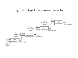
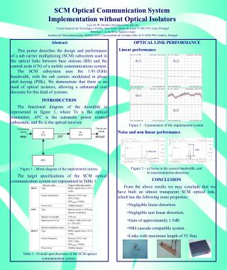
|S22| |S11| |S21| |S21| 50dB -115dBm/Hz SCM Optical Communication System Implementation without Optical Isolators Luís M. M. Mendes (lmendes@estg.iplei.pt) Escola Superior de Tecnologia e Gestão, Alto Vieiro, Morro do Lena, P-2401-951 Leira, Portugal Henrique J. A. da Silva (hjas@co.it.pt) Instituto de Telecomunicações, DEE/FCTUC, Universidade de Coimbra, Pólo II, P-3030-290 Coimbra, Portugal Abstract OPTICAL LINK PERFORMANCE Linear performance This poster describes the design and performance of a sub carrier multiplexing (SCM) subsystem used in the optical links between base stations (BS) and the central node (CN) of a mobile communications system. The SCM subsystem uses the 1.91-2GHz bandwidth, with the sub carriers modulated in phase shift keying (PSK). We demonstrate that there is no need of optical isolators, allowing a substantial cost decrease for this kind of systems. INTRODUCTION The functional diagram of the downlink is represented in figure 1, where Tx is the optical transmitter, APC is the automatic power control subsystem, and Rx is the optical receiver. Figure 2 – S parameters of the implemented system. Noise and non linear performance Figure 3 – a) Noise in the system bandwidth, and b) intermodulation distortion. Figure 1 – Block diagram of the implemented system. The target specifications of the SCM optical communication system are represented in Table 1. CONCLUSION • From the above results we may conclude that we have built an almost transparent SCM optical link, which has the following main properties: • Negligible linear distortion • Negligible non linear distortion, • Gain of approximately 1.5dB • 50 cascade compatible system. • Links with maximum length of 55.3km. Table 1 - Overall specifications of the SCM optical communication system.