Download
1 / 77
860 likes | 993 Views
Dive into VLSI synthesis basics and advanced methods. Explore gate-level simulation, logic synthesis, and power analysis in this comprehensive crash course.

E N D
VLSI Crash CourseSynthesis Li-Yang Huang Jul. 18, 2019
Reference • VLSI Crash Course Synthesis 2018 Yi-Long Liou
Outline • Introduction • Synopsys Graphical Environment • DC-TCL: Introduction • Setting Design Environment • Setting Design Constraints • Synthesis Report and Analysis • Gate-Level Simulation
Outline • Introduction • Synopsys Graphical Environment • DC-TCL: Introduction • Setting Design Environment • Setting Design Constraints • Synthesis Report and Analysis • Gate-Level Simulation
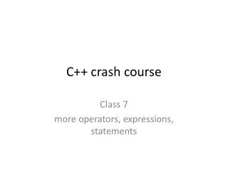
Cell-Based Design Flow Implenentation Verification RTL code always @ (posedgeclk) if(in1==1) a=c+d else a=c-d RTLSimulation Lintcheck code coverageanalysis Logicsynthesis Formal Gate-Levelnetlist Gate level Simulation StaticTimingAnalysis PowerAnalysis Place&Route Formal Gate level Simulation StaticTimingAnalysis PowerAnalysis Post layout Gate-Levelnetlist transistornetlist LVS GDSlayout Extraction DRC Transistor-levelSimulation Transistor-level STA PowerAnalysis Tapeout
Synthesis Design Flow • Develop the HDL design description and simulate the design description to verify that it is correct • Set up the .synopsys_dc.setup file. • Set the appropriate technology, synthetic, and symbol libraries, target libraries, and link libraries. • Set the necessary compilation options, including options to read in the input files and specify the output formats. • Read the HDL design description • Define the design. • Set design attributes • Define environmental conditions • Set design rules • Set realistic constraints (timing and area goals) • Determine a compile methodology Specification RTL CodingPrepare Setting DesignEnvironment Setting DesignConstraint Cell CompileDesign Library Analysis Gate-level Cell-basedNetlist
What is Synthesis • source /usr/cad/synopsys/CIC/synthesis.cshrc
What is Synthesis • Synthesis = translation + optimization + mapping
Logic Synthesis Overview c = a + b + - x / cos sin
HDL Compiler • In schematic view, we can see the Verilog file is translated into Design Compiler as Synopsys design blockwith a GTECH library (the Synopsys default) always @(reset or set) begin if(reset) y=1'b0; else if(set) y=1'b1; end always @(gate orreset) begin if(reset) t=1'b0; else if(gate) t=d; end HDLComipler
Design Compiler • Design Compiler maps Synopsys design block to gate level design with a user specified library Technology Library
Design Compiler Interaction • Three ways to interface Design Vision(GUI) dc_shell (Legacy Interface) GUI Design Compiler (DC) dc_shell–t (TCLInterface) Commandline
RTL Coding Related toSynthesis • Syntax • Each-variable is assigned in the same alwaysblock • Delay is for simulation, not forsynthesis • Memory case: #1 in nonblocking block v.s+notimingcheck • Synopsys full_case /parallel_case • Partition forsynthesis • Separate combinational and sequential part • Separate control and VLSI-designstrategy • Register atinput/output • Special-case needs constraintsetting • Clockgating • Multi-cycle • Falsepath • Asynchronouslogic
STA (Static Timing Analysis) • Sequential circuits are usually constrained by clock specify • Clock cycle >= DFFclk-Qdelay + combinational delay + DFFsetup • DFFclk-Qdelay + combinational delay >= DFFhold CLK pin of Flop1 to D pin ofFlop2 Input port to a D pin ofFlop. Q pin of flop to an outputport Input to outputportthrough purely combinationallogic
Trade-off between Speed and Area • Synthesis is Constraint Driven • Technology Independent
What .synopsys_dc.setupDefined • search_path: the path to search for unsolved reference library or design • target_library: the ASIC technology that the design is mapped to • link_library: the library used for interpreting input description • Any cells instantiated in your HDL code • Wire Load or Operating Condition models used during synthesis • symbol_library: used during schematic generation • synthetic_library: designware library to be used • Other variables
Synopsys Related Files • Set your .synopsys_dc.setup set company "EECS“ set designer "Student“ set search_path “ . $Your_path/CBDK_TSMC018/SynopsysDC/db/ \ ./Memory/ $search_path“ set target_library “ slow.dbfast.db tpz973gvwc.db tpz973gvbc.db \ SRAM2048x20_slow_syn.db SRAM2048x20_fast_syn.db “ set link_library “ * $target_librarydw_foundation.sldb “ set symbol_library “ tsmc18.sdb generic.sdb “ set synthetic_library “ dw_foundation.sldb “ set verilogout_no_tri true set hdlin_enable_presto_for_vhdl "TRUE“ set sh_enable_line_editingtrue keep 100 alias h history
Outline • Introduction • Synopsys Graphical Environment • DC-TCL:Introduction • Setting Design Environment • Setting Design Constraints • Synthesis Report and Analysis • Gate-Level Simulation
Invoke Design Vision • Linux%> dv &
Optimization Using the Design Vision • File/Read or File/Analyze & File/Elaborate • Attributes – set up Design Environment & Goals (record in script sdc files) • Analysis/Report - check if set up is OK • Analysis/Check Design • Tools/Design Optimization • Analysis/Report • File/Save
Read File • Read netlists or other design descriptions into Design Compiler • File/Read • Support many differentformats: • Verilog:.v • VHDL:.vhd • System Verilog:.sv • EDIF • PLA(Berkeley Espresso): .pla • Synopsys internal formats • DB(binary):.db • equation:.eqn • state table:.st Equivalent dc_shell command: dc_shell> read_file –format veriloglab1.v
Analyze & Elaborate • Use analyze and elaborate to bring Verilog or VHDL files into design compiler memory • Analyze does syntax checkingand produces an intermediate .syn .mr .pvlfiles to be stored in a design library • Elaborate looks in the design library for the intermediate file and builds the design up into design compiler memory (as design block)
Analyze • Check VHDL & Verilog for syntax and synthesizability • Create intermediate .syn .mr .pvl files and places them in library specified – design library File/Analyze Equivalent dc_shell command: dc_shell> analyze -format verilog –library WORKcounter.v
Elaborate • Elaborate after analyze to bring design into Design Compiler memory using generic components (GTECH) • Look in the design library for intermediate file for design specified File/Elaborate Equivalent dc_shell command: dc_shell> elaborate counter -architecture verilog -library WORK
Describe the Design Environment • You can use Design Vision to constrain your design
Link Design • Analysis/Link Design • Execute link -all before you optimize your design • To ensure all sub-elements of your hierarchical design are available
Check Design • Analysis/CheckDesign • Execute check_design before youoptimize yourdesign • Two types of messages areissued • Error • Error: In design ‘bcd7segs’, cell ‘decoder’ has more pins than it’s reference ‘d1’ hasports • Warnings • Warning: In design ‘converter’, port ‘A’ is not connected to anynets
Compile the Design • The compile command optimizes and maps the current_design
Report the Design • From Design report and Timing analysis, you can find the set attributes and the results after optimization
Outline • Introduction • Synopsys Graphical Environment • DC-TCL: Introduction • Setting Design Environment • Setting Design Constraints • Synthesis Report and Analysis • Gate-Level Simulation
DC-TCL(Tool Command Language) • TCL script = sequence of commands • .synopsys_setup / my_script.tcl / DUT_syn.sdc • Separate line ; Comments # • GUI interface v.s. DC-TCL command • dv –f script.tcl • TCL Basics • Function arguments • Return string result • Variable Substitution • Syntax: $varName (set a b v.s set a $b) • Nested Commands • Syntax: [commands..] (set a “b-3 is [expr $b-3]”) • get_, all_ command syntax • Search the current design for names of the given object types • Syntax: [get_type [-hierarchy] [name_list]] (set_dont_touch [get_cells * -hier]) • [all_inputs]… dc_shell>helpget_*
Design Objects A circuit that performs one or more logical functions An instance of a design or library primitive within A design The name of the original design that a cell instance “points to” The input or output of a cell input or output of a design The wire that connects ports to pins and/or pins to each other Waveform applied to a port or pin identified as a clock source • Design: • Cell: • Reference: • Port: • Pin: • Net: • Clock:
Design Objects Module TOP(A, B, C, D, CLK, OUT1); input A, B,C, D, CLK; output [1:0] OUT1; wire INV0, INV1, BUS0, BUS1; ENCODER U1 (.AIN(A), .BIN(B), .CIN(C), .DIN(D), .Q0(BUS0), .Q1(BUS1)); INV U2 (.A(BUS0, .Z(INV0))), U3 (.A(BUS1, .Z(INV1))); REGFILE U4(.D0(INV0), .D1(INV1), .CLK(CLK), .Q[0](OUT[0]), .Q[1](OUT[1])); endmodule clock port wire pin cell reference and design pin cannot appear by itself, must accompany with cell
Design Objects Exercise • Make a list of all the ports in the design?{ get_portsA,B,CLK,SUM} • Make a list of all the cells that have the letter “U” in theirname? • { get_cells *U* ADDER/U1, DFF/U2} • Make a list of all the nets ending with “CLK”? { get_nets*CLK CLK} • Make a list of all the “Q” pins in the design? {get_pins */Q U2/Q} • Make a list of all the references? { ADDER,DFF} pin cannot appear by itself, must accompany with cell
Outline • Introduction • Synopsys Graphical Environment • DC-TCL: Introduction • Setting Design Environment • Setting Design Constraints • Synthesis Report and Analysis • Gate-Level Simulation
Why Describesthe Real World Environment • Beware that the defaults are not realisticconditions • Input drive is notinfinite • Capacitive loading is usually notzero • Consider process, temperature, and voltage (PVT) variation • The operating environment affects the components selected from target library and timing through your design. • The real world environment you define describes the conditions that the circuit will operatewithin.
Describing Design Environment (1/2) 1set_operating_conditions 4 3set_driving_cell set_load 5set_input_delay set_wire_load_model 6 set_output_delay 2 create_clock
Describing Design Environment (2/2) • For STA, every node should beknown: • RC value • Inside DUT: Techlib • standardcell/external-IP • wire load model • Outside DUT: • set_drive /set_driving_cell • set_load • I/Odelay • set_input_delay • set_output_delay
1. Setting Operating Condition • Attributes/Operating Environment/OperatingCondition Step 1 Step 2 Name Process Temp Volt Slow 1 125 1.62 Typical 1 25 1.8 Fast 1 -40 1.98 Equivalent dc_shell command: dc_shell> set_operating_conditions -max_library slow -maxslow -min_library fast -min fast
2. Setting Wire Load Model • Wire load model estimates wire capacitance based on chip area & cell fanout • Attributes/Operating Environment/Wire Load Step 1 Step 2 Equivalent dc_shell command: dc_shell> set_wire_load_model –name tsmc18_w10 –libraryslow
Drive Strength & Load for Pads • Input Drive StrengthforPads • Output Load forPads
3. & 4. Input Drive Strength & Output Loading TSMC18:PDIDGZ • Consider for IO Pads (Synthesis wIO) R • Setting Input DriveStrength c pad dc_shell command : dc_shell> set_driving_cell –library tpz973gvwc –lib_cell PDIDGZ –pin {C}[all_inputs] • Setting OutputLoading dc_shell command : dc_shell> set_load [load_of “tpz973gvwc/PDT16DGZ/I” ][all_outputs] • Remember to addIO.db • into target_library in.synopsys_setup
Port Report • Design/Report ports Step 2 Step 1 dc_shell command : dc_shell> report_port -verbose {port_list}
STA (Static Timing Analysis) • Sequential circuits are usually constrained by clock specify • Clock cycle >= DFFclk-Qdelay + combinational delay + DFFsetup • DFFclk-Qdelay + combinational delay >= DFFhold CLK pin of Flop1 to D pin ofFlop2 Input port to a D pin ofFlop. Q pin of flop to an outputport Input to outputportthrough purely combinationallogic
Input/Output Delay • Clock cycle >= DFFclk-Qdelay + c + DFFsetup • Clock cycle >= DFFclk-Qdelay+ a + b +DFFsetup • Input delay = DFFclk-Qdelay+a • Clock cycle >= DFFclk-Qdelay+ d + e +DFFsetup • Output delay = e +DFFsetup
Attention! The step should execute after clock specify 5. Setting Input Delay • Select input ports • Attributes/Operating Environment/Input Delay • Relative to clock trigger time Step 3 Step 1 Step 2 Equivalent dc_shell command: dc_shell> set_input_delay –clock clk –max 6.4 [get_portsin1] dc_shell> set_input_delay –clock clk –min 4.4 [get_portsin1]
Attention! The step should execute after clock specify 6. Setting Output Delay • Select output ports • Attributes/Operating Environment/Output Delay • Relative to clock trigger time Step 3 Step 2 Step 1 Equivalent dc_shell command: dc_shell> set_output_delay –clock clk –max 5.3 [get_portsout1] dc_shell> set_output_delay –clock clk –min 4.4 [get_portsout1]
SDC aboutSetting Design Environment set cycle20 set t_in [expr $cycle/2] set t_out0.5 # Constraintsetting # Clockconstraints create_clock -name clk -period $cycle [get_portsclk] set_fix_hold set_dont_touch_network set_ideal_network set_clock_uncertainty set_clock_latency [get_clocksclk] [get_clocks clk] [get_portsclk] 0.1 [get_clocksclk] 0.5 [get_clocksclk] # Other constraints set_max_fanout 6[all_inputs] # Environmentsetting set_operating_conditions -min_library fast -min fast -max_library slow -max slow set_wire_load_model -name tsmc13_wl10 -libraryslow 1 2 3 4 5 6 set_drive set_load 1 [all_inputs] 1 [all_outputs] set_input_delay $t_in -clock clk [remove_from_collection [all_inputs] [get_portsclk]] set_output_delay $t_out -clock clk[all_outputs]
Outline • Introduction • Synopsys Graphical Environment • DC-TCL: Introduction • Setting Design Environment • Setting Design Constraints • Optimization Constraints • Basic clock constraints concept • Constraints & STA for Special Circuits • Constraint for Power & Area • Design Rule Constraint • Synthesis Report and Analysis • Gate-Level Simulation
Basic Clock Constraints • Clock七大法則: • Period & Waveform • Fix timing issue: • Fix hold • Issue handled in P&R CTS Stage • Don’t touch • Set ideal network (告知DC無skew問題,之後利用uncertainty悲觀模擬解決) • Uncertainty • Skew • Latency • Source latency (option) • Network latency • Transition • Input transition • 測試機台環境→適用whole system情況 DUT is submodule: set driving strength • Clock transition • In P&R,限制其後接的FF數