Download
1 / 12
120 likes | 287 Views
LINAC-BASED PROTON DRIVER. Introduction SPL+PDAC example Elements of comparison Linacs / Synchrotrons. Introduction.

E N D
LINAC-BASED PROTON DRIVER Introduction SPL+PDAC example Elements of comparison Linacs / Synchrotrons
Introduction All proton driver begin with a linear accelerator. In a Linac-based driver, all acceleration is done in the Linac. However a fixed energy synchrotron is still needed for accumulation and bunch compression. At low energy, it makes sense to only accelerate in a linac. Progress in sc resonators are reducing cost. However, at high energy (>5-8 GeV ?), a linac will anyhow be too costly. • What is the limit energy for selecting acceleration in the synchrotron ? • Other arguments ? 2
SPL & PDAC [1/3] SPL (CDR2) characteristics 3
SPL & PDAC [2/3] SPL main goals: • increase the performance of the CERN high energy accelerators (PS, SPS & LHC) • address the needs of future experiments with neutrinos and radio-active ion beams The present R&D programme concentrates on low-energy (Linac4) items, wherever possible in collaboration with other laboratories. 4
SPL & PDAC [3/3] SPL (CDR2) + PDAC characteristics [Extrapolation from PDAC based on the SPL CDR-1] 5
ANNEX 9
Cost comparison Cost Energy 10
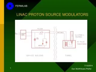
SPL - CDR2 baseline • RF • 704 MHz bulk Niobium cavities • 3 families of cavities : beta =0.5,0.85,1.0 • gradients : 15, 18, 30 MV/m • 5, 6 and 7 cells per cavity • Cold (2K) quadrupoles in the cryomodules, independently aligned from the cavities (to minimize cold/warm transitions and maximize real estate gradient). • Cryomodules of maximum length (between 10 and 15 m), containing n cavities and (n+1) quadrupoles. Diagnostics, steering etc. between cryomodules. • Length of the cavities limited by fabrication and handling considerations. Proposed number of cells per cavity is therefore 5, 6 and 7 for the three sections. • 2 MW max power /coupler • Standardisation of the design after 2 GeV 11
HIP WG: long term alternatives <- * with brightness x2 ** need new injector(s) 12