Download
1 / 25
250 likes | 414 Views
Comparison of Fermilab Proton Driver to Suggested Energy Amplifier Linac. Bob Webber April 13, 2007. Proton Driver Information. Web Site Home Page: http://protondriver.fnal.gov Design Study (Draft, 215 pg.) http://protondriver.fnal.gov/SCRF_PD_V56.doc Director’s Review 2005:

E N D
Comparison of Fermilab Proton Driver to Suggested Energy Amplifier Linac Bob Webber April 13, 2007
Proton Driver Information Web Site Home Page: http://protondriver.fnal.gov Design Study (Draft, 215 pg.) http://protondriver.fnal.gov/SCRF_PD_V56.doc Director’s Review 2005: http://www.fnal.gov/directorate/DirReviews/Dir'sRev_TechnicalReviewoftheProtonDriver_0315.html
Proton Driver to 1 GeV • 50 keV ion source • RFQ to 2.5 MeV • Copper Spoke Cavities to 10 MeV • β= 0.2Superconducting Single Spoke Cavities to ~ 30 MeV • β= 0.4SC Single Spoke Cavities to ~ 125 MeV • β= 0.6SC Triple Spoke Cavities to ~ 400 MeV • β= 0.8 SC “Squeezed” ILC Cavities to > 1 GeV All structures except 1300 MHz “squeezed” ILC cavities are 325 MHz
What of Proton Driver Design Works • Peak energy is not an issue • Peak beam current capabilities are adequate • Low emittance design of PD should satisfy beam loss control requirements of EA Linac
What of PD Design Does Not Work • Ion Source - not designed for CW operation • (LEDA proof-of-principle) • RFQ - not designed for CW operation • (LEDA proof-of-principle) • Room Temp. Cavities (2-10 MeV) - not designed for CW operation • Superconducting Cavity Power Couplers - not designed for CW • Entire RF power system - not designed for CW operation • Pulsed modulator → DC power supplies (LEDA proof-of-principle) • Klystrons (LEDA partial proof-of-principle) • RF Distribution System • Fast Phase Shifters?? • Cryogenics System - not sized for CW RF operation • Power and cooling water utilities infrastructure is inadequate • Controls and Machine Protection System • Radiation Shielding?
Proton Driver RFQ 2.5 MeV -- Length is 3 meters
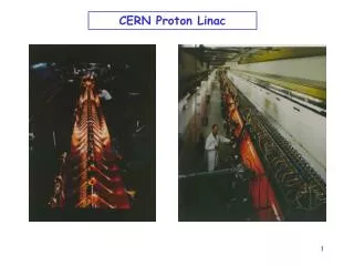
Part of APT RFQ Structure First 1 meter of 8 meter 6.7 MeV LEDA RFQ
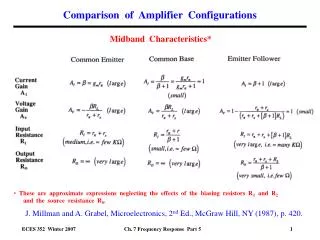
Klystron Comparison While the number of klystrons from PD to EA might only increase by a factor of two, the installed “wall power” and cooling system capability must increase as the ratio of beam power. 10 MW/ 0.25 MW = 40! * LEDA klystrons at this power level were 350 MHz ** Under development for ILC *** availability unknown
1.3 GHz Power Coupler Scale ~40 “squeezed” ILC cavities provide 600 MeV → 1.5 MeV/cavity * 10 mA → 15 kW average per coupler 4 times the nominal ILC coupler design
Proton Driver Building Floor Plan Klystrons x 2+ !! For EA Linac
Building Floor Plan / Utilities Section Power and Utilities x 40 !! For EA Linac
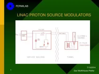
325 MHzFront-EndLinac Single Klystron Feeds SCRF Linac to E > 100 MeV SCRF Spoke Resonator Cryomodules Charging Supply MEBT RFQ Modulator Capacitor / Switch / Bouncer Ferrite Tuners RF Distribution Waveguide 115kV Pulse Transformer 325 MHz Klystron – Toshiba E3740A (JPARC)
Klystron Pulse Transformer Modulator Modulator and Pulse Transformer Pulse Transformer Output Current 2A/div at 36A Bouncer Voltage Capacitor Bank Voltage at 5.6 KV Modulator Output Current 200A/div Modulator Signals at 5.6 KV into Resistive Load February 2, 2007
HINS Room Temp Cavity in Production Body wall roughed in and annealed. Cavity in concept Copper spokes rough machined and annealed Brazed cavity before welding end walls
Bead Pull thru Completed RT CH-01 View thru RF drive port during bead pull Relative field amplitudes Blue – measured Red - predicted
The Challenges • Getting the power to the beam • RF power and accelerator technology • Getting the power out of the beam • Targeting technology and nuclear process science • Controlling beam loss – keeping power where it belongs • Accelerator science and technology • Efficiency, efficiency, efficiency • Wall plug to beam power • Beam transport • Targeting • Cost
HINS Floor Plan in Meson Detector Building ILC HTC Cave Cavity Test Cave RF Component Test Facility Klystron and Modulator Area 60 MeV Linac Cave Existing CC2 Cave Ion Source and RFQ Area 150 ft.
Layout Through Second β=.4 Cryostat Ion Source RFQ MEBT Room Temperature 16-Cavity, 16 SC Solenoid Section 50 KeV 2.5 MeV 10 MeV Two Β=0.2 SSR 9-Cavity, 9-Solenoid Cryostats 20 MeV 30 MeV One Β=0.4 SSR 11-Cavity, 6-Solenoid Cryostat 60 MeV