Download
1 / 22
240 likes | 656 Views
CONSTRUCTION · As mentioned earlier, most of the alternators the winding terminology is slightly different than in case of d.c . generators. · In alternators the stationary winding is called ‘ Stator’ while the rotating winding is called ‘Rotor.

E N D
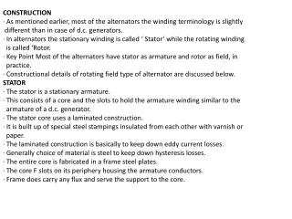
CONSTRUCTION · As mentioned earlier, most of the alternators the winding terminology is slightly different than in case of d.c. generators. · In alternators the stationary winding is called ‘ Stator’ while the rotating winding is called ‘Rotor. · Key Point Most of the alternators have stator as armature and rotor as field, in practice. · Constructional details of rotating field type of alternator are discussed below. STATOR · The stator is a stationary armature. · This consists of a core and the slots to hold the armature winding similar to the armature of a d.c. generator. · The stator core uses a laminated construction. · It is built up of special steel stampings insulated from each other with varnish or paper. · The laminated construction is basically to keep down eddy current losses. · Generally choice of material is steel to keep down hysteresis losses. · The entire core is fabricated in a frame steel plates. · The core F slots on its periphery housing the armature conductors. · Frame does carry any flux and serve the support to the core.
· Ventilation is maintained with the help of holes in the frame. The section of a alternator stator is show the Fig. 6.2
ROTOR · There are two types of rotors used in alternators, i) Salient pole type ant: ii) Smooth cylindrical type. SALIENT POLE TYPE ROTOR
· This is also called projected pole type as all the poles are projected out from the surface of the rotor. · The poles are built up of thick steel laminations. · The pc face has been given a specific shape discussed earlier in case of d.c. · The field winding is provided on the pc shoe. These rotors have large diameter and small axial lengths. · The limiting factor for the size of the rotor is the centrifugal force acting on the member of the machine. · As mechanical strength of salient pole type is less, this is preferred for low speed alternators ranging from 125 r.p.m. to 500 r.p.m. The prime movers used to drive such rotor are generally water turbines and J.C. engines. SMOOTH CYLINDRICAL TYPE ROTOR · This is also called non salient type or non-projected pole type of rotor. · The rotor consists of smooth solid steel cylinder, having number of slots accommodate the field coil. · The slots are covered at the top with the help of steel o manganese wedge. · The un-slotted portions of the cylinder itself act as the poles. · The poles are not projecting out and the surface of the rotor is smooth which maintains uniform air gap between stator and the rotor. · These rotors have small diameters and large axial lengths. · This is to keep peripheral speed within limits
· The main advantage of this type is that these are mechanically very strong and thus preferred for high speed alternators ranging between 1500 to 3000 r.p.m. · Such high speed alternators are called ‘ turbo alternators’. · The prime movers used to drive such type of rotors are generally steam turbines, electric motors. · Let us list down the differences between the two types in tabular form.
DIFFERENCE BETWEEN SALIENT AND CYLINDRICAL TYPE OF ROTOR EXCITATION SYSTEM · The synchronous machines whether alternator or motor are necessarily separately excited machines. · Such machines always require d.c. excitation for their operation. · The field systems are provided with direct current which is supplied by a d.c. souiteat 125 to 600 V. · In many cases the exciting current is obtained from a d.c. generator which is mounted on the same shaft of that of alternator. · Thus excitation systems are of prime importance. Many of the conventional system involves slip rings, brushes and commutators.
BRUSHLESS EXCITATION SYSTEM · With the increase in rating of an alternator, the supply of necessary magnetic fi becomes difficult as the current values may reach upto 4000 A. · If we use convention excitation systems such as a d.c generator whose output is supplied to the alternator f through brushes and slip rings; then problems are invariably associated with slip ring commutators and brushes regarding cooling and maintenance. · Thus modern excitatioi systems are developed which minimizes these problems by avoiding the use of L Such excitation system is called brushless excitation system which is shown in the Fig. 6.5. · It consists of silicon diode rectifiers which are mounted on the same shaft of alternator and will directly provide necessary excitation to the field. · The power required for rectifiers is provided by an a.c. excitor which is having stationary field but rotating armature
· The field of an excitor is supplied through a magnetic amplifier which will control a regulate the output voltage of the alternator since the feedback of output voltage alternator is taken and given to the magnetic amplifier. · The system can be made s contained if the excitation power for the magnetic amplifier is obtained from a small permanent magnet alternator having stationary armature which is driven from the main shaft. · The performance and design of the overall system can be optimized by selecting proper frequency and voltage for a.c. excitor. · The additional advantage that can be obtained with this system is that it is not necessary to make arrangement for spare excitors, generator-field circuit breakers and field rheostats.
PARAMETERS OF ARMATURE WINDING • There are three important parameters of an armature winding of an alternator. These are, • 1. Armature resistance Ra • 2. Armature leakage reactance XL • 3. Reactance corresponding to armature reaction • The equivalent circuit and the concept of synchronous impedance plays an • important role in determining the regulation of an alternator. • ARMATURE RESISTANCE • Every armature winding has its own resistance. The effective resistance of an armature • winding per phase is denoted as Raph f /ph or Ra Wph. • Generally the armature resistance is measured by applying the known d.c. voltage and • measuring the d.c. current through it. The ratio of applied voltage and measured current is • the armature resistance. • But due to the skin effect, the effective resistance under a.c. • conditions is more than the d.c. resistance. Generally the effective armature resistance • under a.c. conditions is taken 1.25 to 1.75 times the d.c. resistance
While measuring the armature resistance, it is necessary to consider how the armature winding is connected whether in star or delta. Consider a star connected armature winding as shown in the Fig. 6.26. When the voltage is applied across any two terminals of an armature winding, then the equivalent resistance is the series combination of the two resistances of two different phase windings. RRY = resistance between R-Y terminals Ra + Ra = 2 Ra Where Ra = armature resistance per phase Fig. Star connected alternator Thus in star connected alternator, the armature resistance per phase is half of the resistance observed across any two line terminals. Consider the delta connected alternator as shown in the Fig. 6.27. When voltage is applied across any two terminals, then one phase winding appears in parallel with series combination of other two.
Hence the equivalent resistance across the terminals is parallel combination of resistances Ra and 2
Introduction • There are numerous practical applications like recording instruments, clocks, teleprinters, • timing devices, computer peripherals which need special motors. The power rating of • such motors is very small. Some of them are even fractional horse power motors hence • these motors are called fractional kW motors. Some of these special purpose motors are • discussed in this chapter. • Reluctance Motor • The reluctance motor has basically two main parts called stator and rotor. • The stator has a laminated construction, made up of stampings. The stampings are slotted • on its periphery to carry the winding called stator winding. The stator carries only one • winding. This is excited by single phase a.c. supply. The laminated construction keeps • iron losses to minimum. The stampings are made up of material like silicon steel which • minimises the hysteresis loss. The stator winding is wound for certain definite number of • poles. • The rotor has a particular shape. Due to its shape, the air gap between stator and rotor is • not uniform. No d.c. supply is given to the rotor. The rotor is free to rotate. The • reluctance i.e. resistance of magnetic circuit depends on the air gap. More the air gap, • more is the reluctance and viceversa. Due to variable air gap between stator and rotor, • when rotor rotates, reluctance between stator and rotor also changes. The stator and rotor • are designed in such a manner that the variation of the inductance of the windings is • sinusoidal with respect to the rotor position. • The construction of the reluctance motor is shown in the Fig. 7.1(a) while the practical • rotor of a reluctance motor is shown in the Fig. 7.1(b)
WORKING PRINCIPLE The stator consists of a single winding called main winding. But single winding can not produce rotating magnetic field. So for production of rotating magnetic field, there must be at least two windings separated by certain phase angle. Hence stator consists of an additional winding called auxiliary winding which consists of capacitor in series with it. Thus there exists a phase difference between the currents carried by the two windings and corresponding fluxes. Such two fluxes react to produce the rotating magnetic field. The technique is called split phase technique of production of rotating magnetic field. The speed of this field is synchronous speed which is decided by the number of poles for which stator winding is wound.
The rotor carries the short circuited copper or aluminium bars and it acts as squirrel cage • rotor of an induction motor. • If an iron piece is placed in a magnetic field, it aligns itself in • a minimum reluctance position and gets locked magnetically. • Similarly in the reluctance • motor, rotor tries to align itself with the axis of rotating magnetic field in a minimum • reluctance position. • But due to rotor inertia it is not possible when rotor is standstill. So • rotor starts rotating near synchronous speed as a squirrel cage induction motor. When the • rotor speed is about synchronous, stator magnetic field pulls rotor into synchronism i.e. • minimum reluctance position and keeps it magnetically locked. • Then rotor continues to • rotate with a speed equal to synchronous speed. Such a torque exerted on the rotor is • called the reluctance torque. • Thus finally the reluctance motor runs as a synchronous • motor. • The resistance of the rotor must be very small and the combined inertia of the • rotor and the load should be small to run the motor as a synchronous motor
MATHEMATICAL ANALYSIS The variation of the inductance of the windings is sinusoidal with respect to rotor position. The variation of the inductance with respect toO is of double frequency and is given by, The stator winding is exciteal by a.c. supply hence = Iflsinwt The energy stored is a function of inductance and given
The flux linkage is given by, Then the torque is given by Substituting the values of i and L, If rotor is rotating at an angular velocity corn then finally the torque equation can be expressed interms of ῳs and ῳm as, The above equation gives instantaneous torque produced. The average torque is zero as average of each term in the above equation is zero. The value of torque is not zero when t ῳ= ῳm and at this condition the magnitude of the average torque is
HYSTERESIS MOTOR This is the synchronous motor which does not require any d.c. excitation to the rotor and it uses non projected poles. It consists of a stator which carries main and auxiliary windings so as to produce rotating magnetic field. The stator can also be shaded pole type. The rotor is smooth cylindrical type made up of hard magnetic material like chrome steel or alrüco for high retentivity. This requires to select a material with high hysteresis loop area. The rotor does not carry any winding. The construction is shown in the Fig. 7.4 (a) while nature of hysteresis ioop required for rotor material . (a) Cross-sectional view of hysteresis motor (b) Hysteresis loop for rotor material When stator is energised, it produces rotating magnetic field. The main and both the windir must be supplied continuously at start as well as in running cor as to maintain the rotating magnetic field. This field induces poles in the rot hysteresis phenomenon is dominant for the rotor material chosen and due to whk pole axis lag behind the axis of rotating magnetic field. Due to this, rotor poles get a towards the moving stator field poles. Thus rotor gets subjected to torque called hysi torque. This torque is constant at all speeds. When the stator field axis moves forwar to high retentivity the rotor pole strength remains maintained. So higher the r higher is the hysteresis torque. Initially rotor starts rotating due to combined effect of hysteresis torque as well a due to eddy currents induced in the rotor. Once the speed is near about the synchronow stator pulls rotor into synchronism. In such case, as relative motion between stator field rotor vanishes, so the torque due to eddy currents vanishes. Only hysteresis t present which keeps rotor running at synchronous speed. The high retentivity, ensures continuous
IMPORTANT DEFINITIONS 1. HOLDING TORQUE It is defined as the maximum static torque that can be applied to the shaft of an excitea motor without causing a continuous rotation. 2. Detent Torque It is defined as the maximum static torque that can be applied to the shaft of an unexcited motor without causing a continuous rotation. Under this torque the rotor comes back to the normal rest position even if excitation ceases. Such positions of the rotor are referred as the detent positions. 3. Step Angle: It is defined as the angular displacement of the rotor in response to each input pulse. 4. Critical Torque: It is defined as the maximum load torque at which rotor does not move when an exciting winding is ener This is also called pullout torque. 5. Limiting Torque: It is defined for a given pulsing rate or stepping rate measured in pulses per second, as the maximum load torque at which motor follows the control pulses without missing any step. This is also called pull in torque. 6. Synchronous stepping rate: It is defined as the maximum rate at which the motor can step without missing steps. The motor can start, stop or reverse at this rate.
Slewing rate: It is defined as the maximum rate at which the motor can step unidirectionally. The slewing rate is much higher than the synchronous stepping rate. Motor will not be able to stop or reverse without missing steps at this rate. Stepper Motor Characteristics The Stepper motor characteristics are classified as 1. Static characteristics and 2. Dynamic characteristics The static are at the stationary position of the motor while the dynamic are under running conditions of the motor. Static Characteristics These characteristics include 1. Torque displacement characteristics 2. Torque current characteristics
Torque-displacement characteristics: This gives the relationship between electromagnetic torque developed and displacement angle 0 from steady state position. These characteristics are shown in the Fig Torque-current characteristics : The holding torque of the stepper motor increases with the exciting current. The relationship between the holding torque and the current is called as torque-current characteristics. These characteristics are shown in the Fig
DYNAMIC CHARACTERISTICS The stepping rate selection is very important in proper controlling of the stepper motor. The dynamic characteristics gives the information regarding torque stepping rate. These are also called torque stepping rate curves of the stepper motor. These curves are shown in the Fig. When stepping rate increases, rotor gets less time to drive the load from one position to other. If stepping rate is increased beyond certain limit, rotor can not follow the command and starts missing the pulses. Now if the values of load torque and stepping rate are such that point of operation lies to the left of curve I, then motor can start and synchronise without missing a pulse. For example, for a load torque of TL, the stepping rate selection should be less than f so that motor can start and synchronize, without missing a step
. The motor is said to be operating in slewing modeBut the interesting thing is that once motor has started and synchronized, then stepping rate can be increased e.g. upto f for the above example. Such an increase in stepping rate from f to f is without missing a step and without missing the synchronism. But beyond f if stepping rate is increased, motor will loose its synchronism. So point A as shown in the Fig. indicates the maximum starting stepping rate or maximum starting frequency. It is defined as the maximum stepping rate with which unloaded motor can start or stop without loosing a single step. While point B as shown in the Fig. indicates the maximum slewing frequence. It is defined as the maximum stepping rate which unloaded motor continues to run without missing a step. Thus area between the curves I and II shown hatched indicates, for various torque values, the range of stepping rate which the motor can follow without missing a step, provided that the motor is started and synchronized. This area of operation of the stepper motor is called slew range To achieve the operation of the motor in the slew range motor must be accelerated carefully using lower pulse rate. Similarly to stop or reverse the motor without loosing acceleration and deceleration of the stepper motor, without losing any step is called Ramping