Eng. 6002 Ship Structures 1 Hull Girder Response Analysis
201 likes | 519 Views
Eng. 6002 Ship Structures 1 Hull Girder Response Analysis. Lecture 5: The shape of Ocean design waves, wave bending moments. Overview. We can consider the wave forces on a ship to be quasi-static. This means that they can be treated as a succession of equilibrium states.

Eng. 6002 Ship Structures 1 Hull Girder Response Analysis
E N D
Presentation Transcript
Eng. 6002 Ship Structures 1Hull Girder Response Analysis Lecture 5: The shape of Ocean design waves, wave bending moments
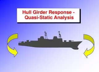
Overview • We can consider the wave forces on a ship to be quasi-static. This means that they can be treated as a succession of equilibrium states. • When a wave passes by a vessel the worst hogging moment occurs when the midbody is on the crest of a wave, and the bow and stern are in the troughs
Overview • The worst sagging moment occurs when the midbody is on the trough, and the bow and stern are on crests • Furthermore, the highest bending moments occur when the wavelength approaches the vessel length
Overview cont. • The design wave for a vessel will therefore have a wavelength equal to the vessel length. • The wave height (peak to trough) is generally assumed to be 1/20th of the wave length (any larger and the wave will break)
Trochoidal Wave Profile • The shape of an ocean wave is often depicted as a sine wave, but waves at sea can be better describaed as "trochoidal". • A trochoid can be defined as the curve traced out by a point on a circle as the circle is rolled along a line.
Trochoidal Waves cont. • The discovery of the trochoidal shape came from the observation that particles in the water would execute a circular motion as a wave passed without significant net advance in their position. • The motion of the water is forward as the peak of the wave passes, but backward as the trough of the wave passes, arriving again at the same position when the next peak arrives. (Actually, experiments show a slight advance of the water with the waves, but that advance is small compared to the overall circular motion.) Source: http://www.dddb.com/rotation.html
Trochoidal Waves cont. For a design wave we assume the following wave is possible • LW=LBP, HW=LBP/20 • We can see that LW=2pR and HW=2r
Trochoidal Waves cont. Which gives • The following formula describes the shape of the waves
Trochoidal Waves cont. Substituting, we have To plot the wave, we simply calculate x and z as a function of q
Trochoidal Waves cont. • The L/20 rule for wave height has been shown to be overly conservative for large vessels and a more modern formula is: • Which gives • Note Hughes gives (for L>350 m)
Calculating Wave Bending Moments • We can now calculate the wave bending moments by placing the ship on the design wave and using the Bonjean curves
Calculating Wave Bending Moments So, to determine the wave bending moment we: • Obtain bonjean curves • At each station determine the still water buoyant forces (using the design draft) • At each station determine the total buoyancy forces using the local draft in that part of the wave • The net wave buoyancy forces are the difference between the total and still water buoyancy forces
Calculating Wave Bending Moments • From here we have a set of buoyancy forces due to waves, which are in equilibrium (recall Lecture 4) • We calculate the moment at midships from the net effect of forces either fore or aft
Computer application • We can also use computer packages (such as Rhino) to find the bending moments • Using a hull model, the buoyant forces on the fore and aft ends of the hull can be determined by the volume and centroid of the submerged volumes at a specific waterline surface • A similar procedure could be used to determine the wave values, but the waterline surface would be the trochoidal wave profile