Download
1 / 17
170 likes | 198 Views
Learn about vertical and horizontal bending moments in ship structures, section modulus calculations, neutral axis identification, and peak stresses. Understand the importance of section modulus and how to calculate it using the parallel axis theorem. Dive into the flexure formula and spreadsheet calculations for hull girders.

E N D
Eng. 6002 Ship Structures 1Hull Girder Response Analysis Lecture 6: Inclined bending and section modulus
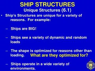
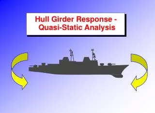
Overview • Up to this point we have assumed that the ship is upright and the bending is in the vertical plane. This is referred to as vertical bending • If the ship is rolling, and at some healing angle, it will be also subjected to horizontal bending. • Since the buoyancy and gravity forces are always in the vertical direction, the bending moment is no longer aligned with the midship section and centreline planes.
Vertical and Horizontal Bending • In the case where the horizontal bending is due entirely to the inclination of the vessel, we may relate the moments as follows • Where My and MZ are the horizontal and vertical bending moments, respectively
Vertical and Horizontal Bending cont. • Recall that the neutral axis identifies a plane along which there is neither tension nor compression • The amount of tensile or compressive stress on any fibre is directly proportional to the distance from the neutral axis to that fibre. • The beam is most highly stressed at the top and bottom, and the neutral axis is located at the centroid of the beam.
The flexure formula • The tensile and compressive stresses in a beam are given by
Total Stress in the hull girder • The stress at point (y,z) is therefore given by: • When we have bending moments in both directions there will be a line of zero axial stress that we can call the heeled neutral axis • To find this axis we solve for the location of zero stress
Total Stress in the hull girder • Which leads to
Total Stress in the hull girder • Now we define • And we have
Total Stress in the hull girder • The angle ψ is the angle of the heeled neutral axis from the y-axis y z
Peak Stresses • The greatest and least stresses will be associated with the maximum and minimum values of y and z (i.e at z = B/2 and y=ydeck) • So we can find the angle of heal corresponding to the worst condition by setting dσ/dθ=0
Peak Stresses • The variable Z is known as the section modulus and typically has a value of 0.5, which leads to a critical heel angle of about 30 degrees
The section modulus • Ships are largely built of plates, and the calculation of the section modulus requires determining the moments of inertia for a collection of rectangular plates
The section modulus • We need the parallel axis theorem to determine the moment of inertia about the neutral axis
The section modulus • The height of the neutral axis is given by
The section modulus • Finally, the moment of inertia calculation is summarized by the followinf formulas
The section modulus • This entire calculation is often performed with a spreadsheet
Section Modulus notes • In general, the two quantities to be calculated are the position of the neutral axis of the section and the moment of inertia about the neutral axis • The choice of the axis zz is arbitrary, but it makes sense to use the keel, since the height of the neutral axis is generally quoted as the height above the keel • Most of the items in the spreadsheet can be treated as rectangles (so I=1/12bt3) • The calculation is usually carried out for one side of the ship only, so results have to be multiplied by 2