Dynamic Macular Distortion Correction: Optical and Computer-Based Approach
Explore techniques to correct macular distortion caused by macular degeneration. Utilizes Amsler Grid, computer software, and optical materials for dynamic, real-time correction. Future prospects involve refractive slabs for correction.

Dynamic Macular Distortion Correction: Optical and Computer-Based Approach
E N D
Presentation Transcript
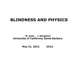
BLINDNESS AND PHYSICS W. Kohn J. Klingshirn University of California, Santa Barbara May 31, 2012 UCLA
General Introduction Macular Degeneration causes a patient’s central visual field to be spatially distorted. • This project’s goals are to: • Quantitatively characterize the distortion perceived by the patient. • Develop optical and computer-based methods to compensate for the perceived macular distortions.
The Amsler Grid • Widely used, non-invasive, diagnostic tool • Dimensions: (10 cm)2 • How used: • Presented 35 cm in front of one eye, head in a chin rest. • Eye focused on highlighted central point, C • A person with a healthy eye perceives the Amsler Grid (AG) and its center precisely as shown on the slide. Fig. 2a: A useful diagnostic tool in Ophthalmology. The center is indicated by a highlighted dot.
Amsler Grid as perceived by a Patient • Fig. 2b: The distorted AG as perceived by a typical patient with macular degeneration • Two abnormal features: • Distortions fo AG lines (however peripheral lines are undistorted) • Dark are(s) with diameter ~2-3 cm
Editing / Diagnosis • MD Patient wears his normal reading glasses (if any). • Amsler Grid (AG) is presented to the patient on a computer monitor, 40 cm ahead. • Head is fixed in a chin rest, Patient is asked to focus on the central point C and maintain focus. • The patient uses simple software and the mouse to straighten distorted “vertical” & “horizontal” lines, until he perceives the grid as “perfect”. (Vertical” and “Horizontal” refer to the edges of the grid.) • During the straightening procedure the computer records the displacements of all intersection points of the AG. • The displacements constitute the spatial diagnosis of the distortions. Figure 3: Using the mouse to edit the lines of the Amsler Grid
Interpolation Displacement of Arbitrary Points Inside the Amsler Grid • At the conclusion of the diagnostic/editing procedure the patient perceives the Amsler Grid without distortions. • Typical reading material consists of ~1000 x 1000 = 106 pixels per page. • Straightening out the lines in the reading material with 106 points is comparable to editing 106 AG grid intersection points. • It is unrealistic for the patient to do this point by point. • Instead we obtain the required displacement vectors for other points within the Amsler Square by suitable interpolation. • The 400 (or fewer) displacements supplied by the diagnosis are used to obtain all other points within the AG using a cell phone sized computer.
Correction By Computer • The reading material is scanned, photographed, or converted into an array of pixels. • Computer software displaces each pixel using the displacements obtained from the diagnostic procedure. • The patient views the corrected text at the appropriate distance. It appears undistorted. What the patient sees without the correction What the patient sees with the correction
Dynamic Compensation • It isn’t sufficient to correct the text for a small area of a printed page. The patient needs to read the entire page. • The solution is to apply the compensation dynamically. • A Computer Based Correction Device • Dynamic Compensation • Anti-Distortion applied in real-time by a handheld computer. To the patient, the image will appear undistorted.
Correction by a Refractive Material • Using the results of our diagnostic procedure, an arbitrary, smooth, sufficiently weak, macular distortion can be corrected by a suitably patterned slab of optical material. • The slab would be made from glass or optical quality plastic, with dimensions on the order of 10 x 10 x 4 cm. • The pattern on the top surface and the plate thickness are chosen so as to cancel the distortions created by the patient’s Macular Degeneration. • L = 10 cm • b = 4 cm • The top surface is custom drilled downward for each patient to a maximum depth of b/2.
Contour Lines of a Patterned Upper-Slab Face Z(x,y) = sin(π x / L) * sin (π y/L)
Prototype Optical Slab Created by UCSB Machine Shop A refractive contoured slab for correcting macular distortion. The reader slides it along over horizontal reading material.
Current Status • Analysis of the diagnostic procedure is complete. • It has been successfully tested on patient ‘Eve’. • The initial test of patient ‘Eve' will be followed up by extensive further testing. • A computer program that creates a dynamic spatial correction has been implemented. • Prototype Optical Slabs that provide a compensating correction have been fabricated.