Download
1 / 12
120 likes | 134 Views
This report provides details on the design and development of the ILD-TPC endplate to accommodate Micro Pattern Gas Detector (MPGD) readout modules while meeting rigidity and material requirements. Finite Element Analysis (FEA) calculations and measurements for deflection and stress are discussed alongside construction challenges and solutions.

E N D
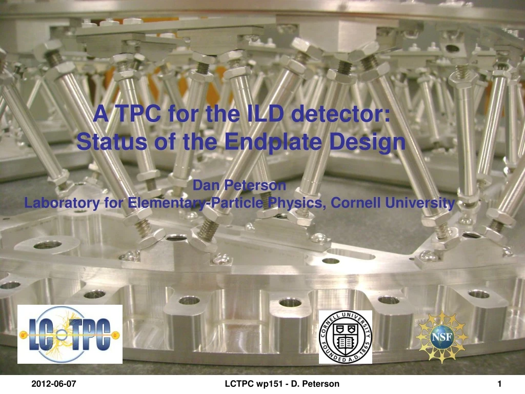
A TPC for the ILD detector: Status of the Endplate Design Dan Peterson Laboratory for Elementary-Particle Physics, Cornell University LCTPC wp151 - D. Peterson
Work at Cornell has been on the development of the endplate and module mechanical structure to satisfy the material and rigidity requirements of the ILD. The ILD TPC has dimensions outer radius 1808 mm inner radius 329 mm half length 2350 mm This is a reminder of some of the points from the full report presented at the LCTPC group meeting 2012-03-26 . LCTPC wp151 - D. Peterson
Goals of the ILD TPC endplate Detector module design: Endplate must be designed to implement Micro Pattern Gas Detector (MPGD) readout modules. Modules must provide near-full coverage of the endplate. Modules must be replaceable without removing the endplate. Low material - limit is set by ILD endcap calorimetry and PFA: 25% X0 including readout plane, front-end-electronics, gate 5% cooling 2% power cables 10% mechanical structure 8% Rigid - limit is set to facilitate the de-coupled alignment of magnetic field and module positions. Precision and stability of x,y positions < 50μm Thin - ILD will give us 100mm of longitudinal space between the gas volume and the endcap calorimeter. LCTPC wp151 - D. Peterson
FEA calculations of deflection and stress (stress is not shown) Endplate deflections were calculated with finite element analysis (FEA). Endplate Support: outer and inner field cages Maximum deflection 0.00991 mm/100N Calibration: 100N is the force on LP1 due to 2.1 millibar overpressure ratio of areas: (area of ILD)/(area of LP1) =21.9 deflection for 2.1 millibar overpressure on the ILD TPC endplate (2200N) = 0.22 mm Without the space-frame structure, the simple endplate deflects by 50mm. Much of the remaining part of this study is to validate that this calculation is accurate for the complicated structure. LCTPC wp151 - D. Peterson
The first of two LP2 space-frame endplates is assembled (Friday, 25-March). measuring the deflection The FEA predicts a longitudinal deflection of 23 microns / 100 N load. (with the load applied at the center module.) LCTPC wp151 - D. Peterson
Comparison of deflection for LP1/LP2 endplates: FEA vs. measurements Measured mass of the LP2 space-frame endplate: 8.8kg ??? screws Measured deflection: 27.6 microns (preliminary measurement) a more accurate measurement requires a larger load height of outer rim is fixed at only 4 places, could use a stiffer module back-frame, there may be loose screws in the strut mounts calculated measured mass material deflection stress deflection kg %X0 microns Mpa microns (100 N) (yield: 241) (100 N) LP1 18.87 16.9 29 1.5 33 Lightened 8.93 8.0 68 3.2 Al-C hybrid Al 7.35 7.2 (68-168) (3.2-4.8) (channeled plus fiber) C 1.29 Channeled Al 7.35 6.5 168 4.8 Space-Frame 8.38 7.5 23 4.2 28 (strut or equivalent plate) LCTPC wp151 - D. Peterson
This is a fully functional replacement for LP1endplate, shown with the lightened module back-frames. One will be sent to DESY, where we can study system operation. Another will be kept for measurements of long term stability and lateral strength/accuracy. An issue: there are difficulties installing the mounting brackets. Some minor modifications will make this easier. A non-issue: alignment of the struts is easier than anticipated. fine and coarse thread screws, 10-32, 10-24, metric equiv: 4.88-0.794 4.88-1.058 difference: 96 turns/inch, 0.264mm/turn LCTPC wp151 - D. Peterson
Issues for the construction of the ILD endplate Machining: we are looking at a 12 foot travel milling machine. They exist, but global tolerance is ~125 microns Handling: inner and outer plates will require fixtures for handling and shipping Stress relief: requires a 12 foot square tub of liquid nitrogen (solvable). Assembly alignment: I use a ground plate as an assembly jig. Does not scale to ILD. Solvable, set up stands with optical levels. Assembly: ~3000 struts, 5 minutes each, 250 hours Endplate alignment: not a 3000 degree of freedom exercise only ~5 struts must be changed at any one time. LCTPC wp151 - D. Peterson
From Agenda posted 2012-06-05 some comments… (a) Rigidity/deformation of field cage and endplates for given scheme of TPC support. Studies can be performed on the current model. I can create a rigid ceiling from which to hang the endplate, attaching rods for the vertical supports. (red) Forces can be applied to various locations. I only must add little fictitious brackets with defined surfaces. (b) Structure of the central cathode electrode and HV supply/cable The assembly makes it difficult to secure the central cathode to both the inner and outer field cages. The central cathode will require inner and outer support hoops. The inner radius, overall, is 330 mm. It would be possible to access the connection of the inner radius of the central cathode, to the inner field cage, through the inner field cage, after the inner field cage is attached to the endplates. LCTPC wp151 - D. Peterson
(c) Procedure of TPC assembly and installation I believe the readout modules are installed from the outside, after the mechanical endplates are attached to the field cage. There would be a support structure stiffening the outer field cage during the installation of the (in this order) central cathode , which is first connected to the outer field cage, mechanical endplates, inner field cage, connection of the central cathode to the inner field cage. Note that the inner field cage is an integral part of the structure. We have already decided that it will constrain the endplates at the inner radius. The inner field cage is floating between the endplates, but constraining the separation distance. After the central cathode is attached to the inner field cage, we must be careful with longitudinal motion of the inner field cage, w.r.t. the outer field cage. During installation, we will probably have extra supports on the mechanical endplates if there is insufficient rigidity during movement. LCTPC wp151 - D. Peterson
(d) Monitor (deformation/misplacement) We will need a laser system monitoring points on the endplate. (e) Support structure of the silicon envelopes There is probably sufficient strength in the outer and inner flanges of the mechanical endplates to support the silicon. If there is a proposal: components, mounting frame, weights, the deflection can be modeled. LCTPC wp151 - D. Peterson
(f) Material budget of endcap (g) Cables (number of cables + cross sections per endcap for mechanical model of ILD) from slide 3: Low material - limit is set by ILD endcap calorimetry and PFA: 25% X0 including readout plane, front-end-electronics, gate 5% cooling 2% power cables 10% mechanical structure 8% LCTPC wp151 - D. Peterson