Download
1 / 14
140 likes | 373 Views
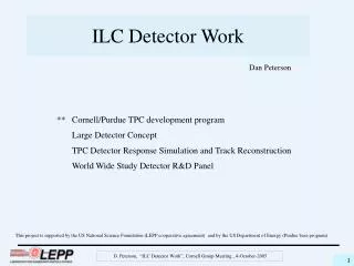
ILC Detector Work. Dan Peterson. ** Cornell/Purdue TPC development program Large Detector Concept TPC Detector Response Simulation and Track Reconstruction World Wide Study Detector R&D Panel.

E N D
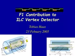
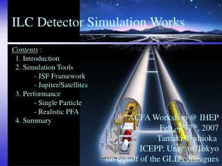
ILC Detector Work Dan Peterson ** Cornell/Purdue TPC development program Large Detector Concept TPC Detector Response Simulation and Track Reconstruction World Wide Study Detector R&D Panel This project is supported by the US National Science Foundation (LEPP cooperative agreement) and by the US Department of Energy (Purdue base program) D. Peterson, “ILC Detector Work”, Cornell Group Meeting , 4-October-2005
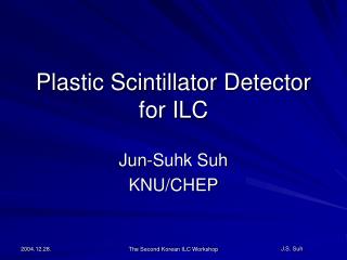
TPC Cornell University Purdue University D. P. Peterson G. Bolla L. Fields I. P. J. Shipsey R. S. Galik P. Onyisi January 2005: construction completed, recorded first events 14.6 cm ID field cage - accommodates a 10 cm GEM 64 cm drift field length 22.2 cm OD outer structure (8.75 inch) D. Peterson, “ILC Detector Work”, Cornell Group Meeting , 4-October-2005
MPWC and GEM amplification The readout module including the amplification device mounted on pad board 10 cm The instrumented readout area is ~2cm x7 cm , 32 pads. The biased area is 10cm square. ( This pad board allows ~3 x 9 cm , 62 pads. ) D. Peterson, “ILC Detector Work”, Cornell Group Meeting , 4-October-2005
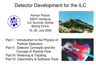
TPC Readout End details Visible: field cage HV distribution field cage termination wire gas-amplification pad board pad biasing boards signal ribbon cable Biasing: drift: 300V/cm @ termination: -900V ( 1.0 cm ) grid: -600V ( 0.5 cm ) anode: +550V ( 0.5 cm ) pads: -2000V D. Peterson, “ILC Detector Work”, Cornell Group Meeting , 4-October-2005
single GEM single GEM gas amplification CERN GEM mounted, tested by Purdue installed 11-March biasing: field cage, -20kV, 300 V/cm termination: -900V GEM voltage: -400V (GEM bottom: at ground) (Gas amplification ~100.) pads: +1500 V Electric fields: field termination – GEM top:0.5 cm , 0.96 kV/cm induction gap: 0.3 cm, 5 kV/cm D. Peterson, “ILC Detector Work”, Cornell Group Meeting , 4-October-2005
MWPC event (typical) ArCO2 (10%) , 300V/cm 25 MHz , 40 ns 2048 time buckets (81.92 ms) D. Peterson, “ILC Detector Work”, Cornell Group Meeting , 4-October-2005
single-GEM event Note the 1 mv scale. Gas amplification is about 100 ArCO2 (10%) , 300V/cm 25 MHz , 40 ns 2048 time buckets (81.92 ms) D. Peterson, “ILC Detector Work”, Cornell Group Meeting , 4-October-2005
GEM event after smoothing and common noise subtraction ArCO2 (10%) , 300V/cm 25 MHz , 40 ns 2048 time buckets (81.92 ms) D. Peterson, “ILC Detector Work”, Cornell Group Meeting , 4-October-2005
charge width This is influenced by the common “noise” subtraction.) D. Peterson, “ILC Detector Work”, Cornell Group Meeting , 4-October-2005
hit resolution (5mm pad) find tracks - require coincident signals in 6 layers locate maximum PH pad in each layer find PH center using maximum PH pad plus nearest neighbors ( 2 or 3 pads in the “hit” ) require the hit pulse height sum to have 70% of layer pulse height sum require 5 layers with interior hits ( Max. ph pad is NOT on the edge.) fit to a line may eliminate 1 hit with residual > 2.5mm ( Still require 5 layers with interior hits.) refit resolution is ~ 900 mm, 0 to 40cm drift D. Peterson, “ILC Detector Work”, Cornell Group Meeting , 4-October-2005
Future: Fine Segmentation Pad Board We will increase the DAQ by 16 channels. 48 channels will allow … 2 rows of 2mm pads plus 4 rows of 5mm pads for track definition Or.. 1 row of 2mm pads 4 rows of 5mm pads 8 channels for positive ion measurement D. Peterson, “ILC Detector Work”, Cornell Group Meeting , 4-October-2005
Future: Ion Feedback Measurement Positive ions are created in the amplification and drift back into the field cage. This is bad because the positive ions in the field cage can distort the drift field. The GEMs and MicroMegas should have reduced fraction of feedback. Measurements have been made using the current at the cathode. We would collect the positive signal on the field cage termination. D. Peterson, “ILC Detector Work”, Cornell Group Meeting , 4-October-2005
Ion Feedback Measurement D. Peterson, “ILC Detector Work”, Cornell Group Meeting , 4-October-2005
Other Activity the WWSOC Detector R&D Panel an international panel of 9 people on which I agreed to serve ( I should have taken B.D.’s advice.) https://wiki.lepp.cornell.edu/wws/bin/view/Projects/WebHome the Large Detector Concept concept, one of the 3 concepts recognized by the GDE. thinking about magnetic field measurement requirements < 10-5 I agreed to “take charge of the section on tracking performance”. (Again, I ignored B.D. and will pay for it.) “TPC response simulation and reconstruction efficiency” - running DOIT on 3 million hits per event. D. Peterson, “ILC Detector Work”, Cornell Group Meeting , 4-October-2005