Download
1 / 10
130 likes | 339 Views
1. Introduction – Concept of Stress. Concept of Stress. The main objective of the study of the mechanics of materials is to provide the future engineer with the means of analyzing and designing various machines and load bearing structures.

E N D
1 Introduction –Concept of Stress
Concept of Stress • The main objective of the study of the mechanics of materials is to provide the future engineer with the means of analyzing and designing various machines and load bearing structures. • Both the analysis and design of a given structure involve the determination of stresses and deformations. This chapter is devoted to the concept of stress.
Review of Statics • The structure is designed to support a 30 kN load • The structure consists of a boom and rod joined by pins (zero moment connections) at the junctions and supports • Perform a static analysis to determine the internal force in each structural member and the reaction forces at the supports
Conditions for static equilibrium: Structure Free-Body Diagram • Structure is detached from supports and the loads and reaction forces are indicated • Ay and Cy can not be determined from these equations
Consider a free-body diagram for the boom: substitute into the structure equilibrium equation • Results: Reaction forces are directed along boom and rod Component Free-Body Diagram • In addition to the complete structure, each component must satisfy the conditions for static equilibrium
Joints must satisfy the conditions for static equilibrium which may be expressed in the form of a force triangle: Method of Joints • The boom and rod are 2-force members, i.e., the members are subjected to only two forces which are applied at member ends • For equilibrium, the forces must be parallel to to an axis between the force application points, equal in magnitude, and in opposite directions
Can the structure safely support the 30 kN load? • At any section through member BC, the internal force is 50 kN with a force intensity or stress of dBC = 20 mm • From the material properties for steel, the allowable stress is Stress Analysis • From a statics analysis • FAB= 40 kN (compression) • FBC = 50 kN (tension) • Conclusion: the strength of member BC is adequate
For reasons based on cost, weight, availability, etc., the choice is made to construct the rod from aluminum (sall= 100 MPa). What is an appropriate choice for the rod diameter? Design • Design of new structures requires selection of appropriate materials and component dimensions to meet performance requirements • An aluminum rod 26 mm or more in diameter is adequate
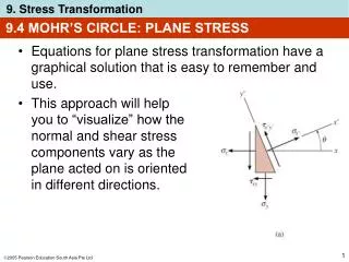
The resultant of the internal forces for an axially loaded member is normal to a section cut perpendicular to the member axis. • The force intensity on that section is defined as the normal stress. • The normal stress at a particular point may not be equal to the average stress but the resultant of the stress distribution must satisfy Axial Loading: Normal Stress • The detailed distribution of stress is statically indeterminate, i.e., can not be found from statics alone.
A uniform distribution of stress in a section infers that the line of action for the resultant of the internal forces passes through the centroid of the section. • If a two-force member is eccentrically loaded, then the resultant of the stress distribution in a section must yield an axial force and a moment. Centric & Eccentric Loading • A uniform distribution of stress is only possible if the concentrated loads on the end sections of two-force members are applied at the section centroids. This is referred to as centric loading. • The stress distributions in eccentrically loaded members cannot be uniform or symmetric. To be continued…