Download
1 / 6
60 likes | 177 Views
This guide details the MixAnew System™, focusing on the seamless integration of tube handling and dynamic mixing processes. With components such as the nozzle former, tube opener, and manifold sealing systems, the MixAnew System™ ensures efficient mixing and dispensing of materials. The processes are co-linear, facilitating efficient mixing within the tube. Key features include piston-driven agitators for side-to-side mixing, toggle-actuated tube clamps, and control screens for single-shot dispensing and continuous operations. This document serves as an essential resource for understanding and utilizing the MixAnew System™ effectively.

E N D
TM MixAnew System Process Description
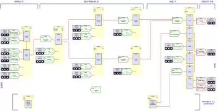
Guide Block & Cushion Assembly Nozzle Former Tube Opener Tube Closer Manifold Seal Tube Storage Component Injection Manifold Dynamic Mixer Process Block Diagram of the MixAnew System TM Tube Handling Process Dynamic Mixing Process Discharge Note: The tube handling and dynamic mixing processes are colinear, with the dynamic mixing process occurring inside the tube handling process.
Components of the MixAnew System TM Manifold Seal Tube Closer Tube Opener Nozzle Former Guide Block & Cushion Assembly Tube Storage Dynamic Mixer Discharge Component Injection Manifold
Mix tube path of MixAnew System Prototype Model A Mix tube path of MixAnew System Prototype Model A TM Tube is closed and sealed around injector tip Tube former and applicator tip Component Injector Manifold Mixing zone Mix Tube Storage Tube Opens Guide Block and Cushion Assembly
Agitator System of MixAnew System Prototype Model A TM Piston driven spring steel agitators are mounted on alternating sides to provide side to side mixing and are sequenced to provide pumping action. Toggle Actuated Tube Clamp and Seal Mixture Flow
Mixer Control Screens Single shot dispense Add extra mix cycles Continuous dispense Purge mix zone Equalize feed lines