Download
1 / 17
200 likes | 480 Views
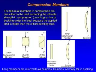
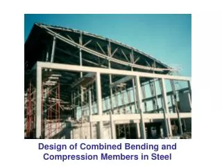
Design of Combined Bending and Compression Members in Steel. Combined stresses. Bi-axial bending. Bending and compression. Multi-story steel rigid frame.

E N D
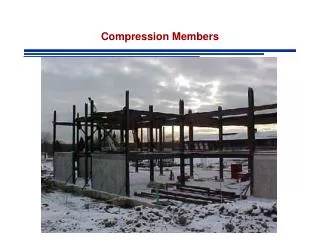
Combined stresses Bi-axial bending Bending and compression
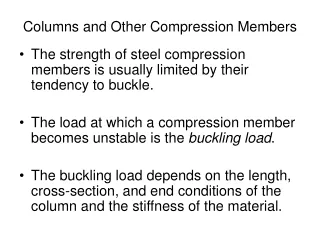
Rigid frames, utilizing moment connections, are well suited for specific types of buildings where diagonal bracing is not feasible or does not fit the architectural design • Rigid frames generally cost more than braced frames (AISC 2002)
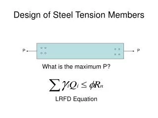
Pf fa = Pf / A neutral axis x fbx = Mfx / Sx Mfx x y fby = Mfy / Sy Mfy y fmax = fa + fbx + fby < fdes ( Pf / A ) + ( Mfx /Sx ) + ( Mfy / Sy ) < fdes (Pf / Afdes) + (Mfx /Sxfdes) + (Mfy / Syfdes) < 1.0 (Pf / Pr) + (Mfx /Mr) + ( Mfy / Mr) < 1.0
Class 1 steel sections (Pf / Pr) + 0.85(Mfx /Mr) + 0.6( Mfy / Mr) < 1.0 other steel sections (Pf / Pr) + (Mfx /Mr) + ( Mfy / Mr) < 1.0 Cross-sectional strength Pf/Pr 1.0 1.0 Mf/Mr
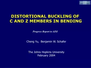
Slender beam-columns • What if column buckling can occur ? • What if lateral-torsional buckling under bending can occur ? Use the appropriate axial resistance and moment resistance values in the interaction equation
P δo δmax P Moment amplification PE = Euler load
Interaction equation Axial load Bending about x-axis Bending about y-axis ω1 = moment gradient factor (see next slide)
Moment gradient factor for steel columns with end moments M1 ω1 = 0.6 – 0.4(M1/M2) ≥ 0.4 i.e. when moments are equal and cause a single curvature, then ω1 = 1.0 and when they are equal and cause an s-shape, then ω1 = 0.4 M2
Steel frame to resist earthquake forces Warehouse building, Los Angeles
Moment gradient factor for other cases v ω1 = 1.0 ω1 = 0.4 ω1 = 1.0 ω1 = 0.85 ω1 = 0.6
Design of steel beam-columns • Laterally supported • Cross-sectional strength • Supported in the y-direction • Overall member strength • Use moment amplification factor • Use buckling strength about x-axis (Crx) • Laterally unsupported • Buckling about y-axis (Cry) • Lateral torsional buckling (Mrx) • Use moment amplification factors • Usually the most critical condition Note: Mry never includes lateral-torsional buckling
Example of different support conditions This column unsupported These two columns supported in y-direction by side wall x direction y direction